Operating a Limitorque MX series electric actuator comes down to three things: the red selector (LOCAL/STOP/REMOTE), the black control knob (OPEN/CLOSE/STOP) and the SETUP menu. Three numbers to remember first: torque settings are adjustable from 40% to 100% of rated torque in 1% steps; the gearbox runs on Exxon Teresstic SHP320 synthetic oil (approx. -30 to 120 °C); and oil charges range from 256 ml (MX-05) to 1183 ml (MX-40). This article condenses an operating procedure used at a petrochemical pipeline company — manual/electric changeover, local and remote control, limit calibration, troubleshooting and lubrication — into a field reference.
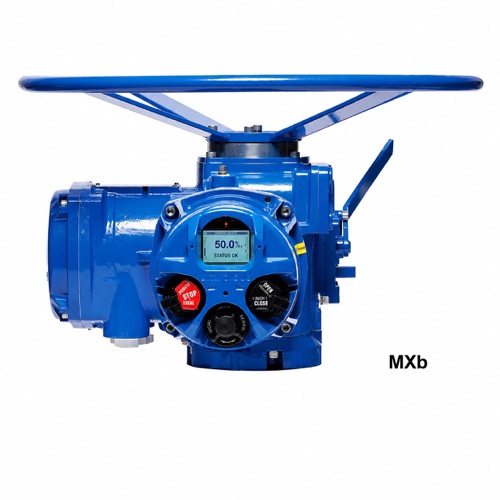
Limitorque MXb multi-turn intelligent actuator (image: e4industrial.com)
To operate by handwheel, push the clutch handle down while slowly turning the handwheel until the clutch is fully engaged. The handle springs back, but a spring-loaded pin holds the clutch in handwheel mode. To return to motor operation, simply energize the motor — the pin trips, the clutch disengages from the handwheel and re-engages the gear drive. To prevent unauthorized manual operation, the clutch handle can be padlocked in the "motor" position.
Check that supply voltage matches the nameplate. Phase rotation does not need to be checked — every MX unit has automatic phase correction. After power-up, do not operate the actuator until its settings and configuration are confirmed correct for the application.
Set the red selector to LOCAL and choose OPEN or CLOSE with the black knob. In maintaining mode the actuator keeps running when the knob is released; turning the red selector to STOP halts it at any time. In jogging (non-maintaining) mode, hold the black knob at OPEN or CLOSE for as long as required — releasing it stops the actuator, letting you inch the valve to any intermediate position.
With the red selector at REMOTE, local OPEN/CLOSE is inhibited. Moving the red selector to STOP unconditionally stops the actuator regardless of the remote signal. All three positions (LOCAL/STOP/REMOTE) can be padlocked.
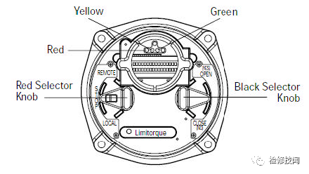
MX control faceplate: red selector (LOCAL/STOP/REMOTE), black control knob, LCD and LEDs
In normal operation the LCD shows the valve position in percent (%OPEN) on the top line and STATUS OK, ALARM or STATUS MESSAGE on the bottom line. The LED meanings are:
| LED state | Meaning |
|---|---|
| Red solid | Valve fully open |
| Red flashing | Valve opening |
| Green solid | Valve fully closed (factory default: green = close direction) |
| Green flashing | Valve closing |
| Yellow solid | Actuator in LOCAL or STOP |
Setup is used for first-time configuration: ① set the red selector to STOP; ② within 10 seconds turn the black knob YES→NO→YES, pausing about 1 second per position; ③ the LCD shows SETUP for 10 seconds — if nothing is done it resets; ④ answer each prompt with YES/NO; ⑤ answer YES to EXIT SETUP. Exiting by moving the red selector from STOP to LOCAL or REMOTE works at any time, and all changes are saved to non-volatile memory, surviving power loss. Note: 15 minutes of inactivity in SETUP causes a reset, and cutting power during SETUP invalidates the current configuration. VIEW SETTING lets you browse up to 16 setting groups without a password, but not change them.
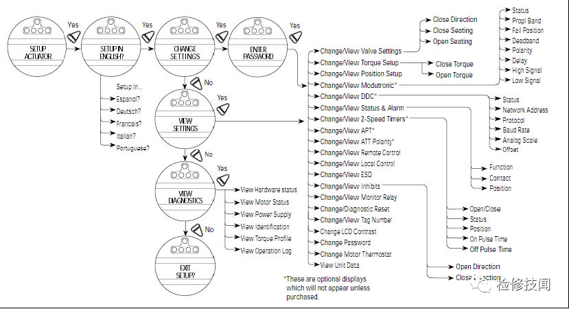
MX menu flowchart: SETUP → ENABLE → CHANGE SETTINGS → VIEW SETTINGS → VIEW DIAGNOSTICS, with the 21 setting branches
| # | Setting | # | Setting |
|---|---|---|---|
| 1 | Valve settings | 12 | ESD emergency shutdown |
| 2 | Torque settings | 13 | Interlock ("inhibit") |
| 3 | Position settings | 14 | Monitor relay |
| 4 | Modutronic | 15 | IR address |
| 5 | DDC | 16 | Diagnostic reset |
| 6 | Status & alarm contacts | 17 | TAG number |
| 7 | Two-speed timer | 18 | LCD contrast |
| 8 | SPT position transmitter | 19 | Password |
| 9 | ATT torque transmitter | 20 | Thermostat switch |
| 10 | Remote control | 21 | Limits (consult factory) |
| 11 | Local control | — | — |
Close direction: most valves close clockwise (CW) viewed from the handwheel side. Observe the rotation while closing by hand and select the direction with NO/YES (default = CW close). Seating: ball, butterfly, gate and knife-gate valves use POSITION seating limits in both directions; backseat valves require a TORQUE limit in the opening direction (default = position to seat in both directions).
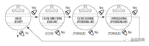
Valve setup flowchart: close direction (CW/CCW) → close seating (position/torque) → open seating
Opening and closing torque can each be configured from 40% to 100% of nameplate rating in 1% steps. Scroll to the target percentage with NO and confirm with YES. If the maximum is below 100% (e.g. 85%), the factory has applied a TORQUE LIMITED setting to protect the valve and actuator — do not alter it without consulting the manufacturer; the recommended value is normally used.
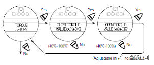
Torque setup: close and open torque independently adjustable 40%–100%
Closing limit by handwheel: ① select YES at SET CLOSE POSITION LIMIT; ② engage the manual device, confirm the valve is fully closed, then turn the handwheel one turn toward open so the drive gears take up mesh; ③ with the valve correctly seated select YES — SAVE CLOSE LIMIT OK confirms calibration. Verification: turn the handwheel toward open — the close LED should extinguish within one turn; returning toward close, the LED should light exactly 1/2 to 1 turn before the fully closed position. The opening limit follows the same procedure in reverse. Electric calibration is also possible: while CLOSE VALVE OK / OPEN VALVE OK is displayed, set the red selector to LOCAL and run the actuator electrically to the limit, then return the selector to STOP.
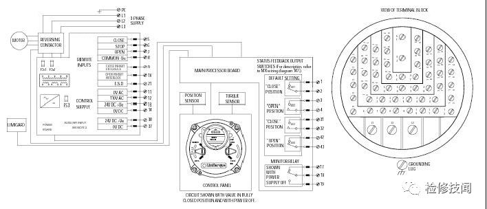
MX control unit wiring: three-phase supply/contactor, fuses FS1–FS3, main processor board, status/feedback outputs and terminal block
| Symptom | Checks |
|---|---|
| 110V AC / 24V DC control supply not reaching terminals | Switch off mains, remove the control-box lid; check fuses FS1/FS2 (600V, 1A, fast, 10.3×38.1mm) and FS3 (250V, 0.1A, time-delay, 5×20mm glass); terminals 11/12 are 110V AC digital inputs, 13/14 are 24V DC (10W); re-energize and test — if still dead, check for external short circuit or overload |
| Local control inoperative | Red selector at LOCAL? Motor runs but output shaft does not — check the clutch handle is in motor position; check the LCD for alarms; if the motor runs but nothing moves, check for a jammed valve; check the interlock signal; an overheated motor recovers when cooled |
| Remote mode inoperative | Confirm the unit is not locked in local; red selector at REMOTE? Check the ESD signal at the terminals (adjustable when "ESD active" is displayed); if previously operated locally, the fault is likely in the remote circuit — check cables and wiring diagram |
| Suspected stuck valve | Check position limits (the motor should stop just before end of travel — recalibrate if necessary); check torque settings; check stem and thrust-bearing lubrication — long periods without operation cause rust, so exercise the valve with the handwheel; stroke it fully several times |
| Actuator turns, valve does not | Check the clutch is in motor position; check the stem nut is properly fitted to the actuator base; check the drive nut connection to the stem; check the key is in its keyway |
| Valve will not close tightly | Check mechanical stops on any quarter-turn gearbox; check calibrated position limits match valve travel; check whether closing should be torque-seated rather than position-seated; check closing torque is high enough to overcome process conditions; check for obstructions |
For diagnosis, the LCD can also step through VIEW DIAGNOSTICS → HARDWARE STATUS → MOTOR STATUS → POWER SUPPLY → IGNITION/COMMUNICATION → OPERATION LOG.
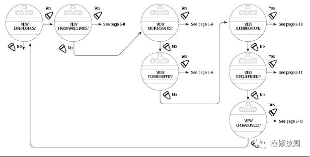
Diagnostics menu: hardware status, motor status, power supply, communication and operation log
MX actuators are oil-lubricated with Exxon Teresstic SHP320 synthetic oil (approx. -30 to 120 °C). Fill quantities by model — do not overfill, to avoid pressurizing the gearbox:
| Model | Oil charge (fl oz) | Oil charge (ml) |
|---|---|---|
| MX-05 | 10 | 256 |
| MX-10 | 16 | 473 |
| MX-20 | 30 | 887 |
| MX-40 | 40 | 1183 |
Oil level: open the top fill plug; with the horizontal base mounted, the level should be visible within the approx. 1-inch inspection hole — top up if low. Under normal conditions MX is maintenance-free; the manufacturer recommends checking the oil level every 1,000,000 revolutions or 3,000 operating cycles, and checking oil quality regularly under frequent operation or high temperature. For valves operated only occasionally, schedule periodic exercising: silt and corrosion sharply increase valve operating torque and are a common cause of torque-trip stoppages.
Need Limitorque series actuators or Chinese equivalents sized and quoted? Submit an RFQ.






