During sample testing of electric actuators, accurate output-torque measurement is critical to product improvement — yet field tests had recorded the anomaly of "maximum controlling torque exceeding stall torque" (theory holds stall torque at 1.3–1.8× the maximum controlling torque). This paper traces the root cause to a sampling rate below the torque-signal slew rate, and proposes high-speed sampling with the AD7731 (6400Hz) plus a three-point rolling Newton-interpolation algorithm, achieving a measured sampling accuracy of 2.5‰. Compiled from a Chinese academic paper; equations and test data reproduced from the original (formula images re-processed from dark scans).
Dynamic torque should be analyzed with random-process data-processing theory, characterized in the amplitude domain by the amplitude probability function and the cumulative amplitude probability function, yielding: (A) the probability that the instantaneous torque T(t) lies within (T, T+ΔT); (B) the probability that T is below a given value T₁; (C) mean, mean-square, variance and standard deviation.
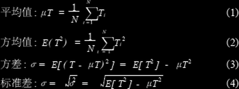
Statistical characteristic definitions (Eqs. 1–4)
Torque measurement principle: after torsion of an elastic straight circular shaft, radii on the cross-section remain straight; shear strain is proportional to radial distance, and by Hooke's law so is shear stress. With shear stress τ at radius r, the stress on an area element da and its moment about the axis follow the mechanics-of-materials formulas; total torque is the integral over the section.
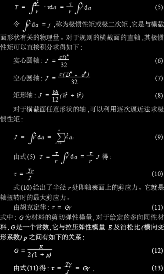
Polar moment of inertia and shear-stress formulas (Eqs. 5–13): solid shaft, hollow shaft, rectangular shaft
By Eq. (14), measuring torque on a given shaft requires the shear strain τ at 45° to the axis — difficult to measure directly. Torque measurement therefore uses the strain at 45° on the shaft surface: pure shear on the surface equals a stress state of tension σ at 45° and equal compression −σ at 135°.
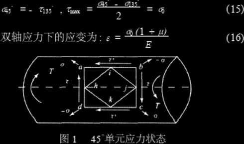
Fig. 1 Pure shear stress state on the shaft surface: (a) cross-section axonometry; (b) strain element
The deformation of the unit square is shown in Fig. 2: diagonal AB becomes AB′; from the increment the 45°-direction strain-to-torque relation is derived.
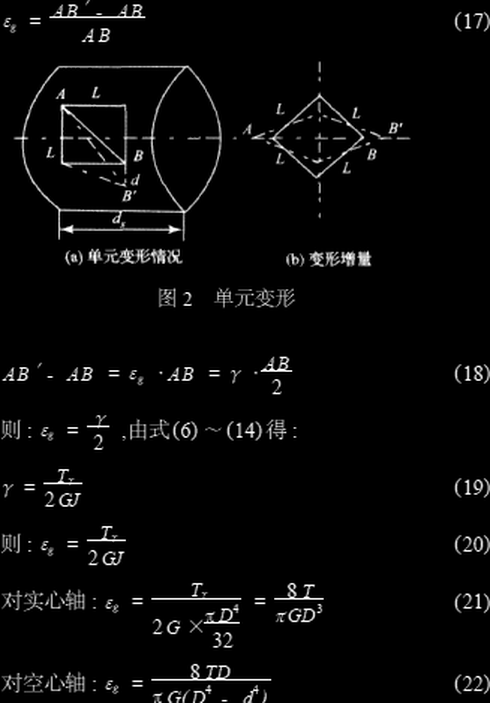
Fig. 2 Unit deformation, and Eqs. 14–22 (solid shaft T = πD³εg/16; hollow shaft per inner/outer diameters)
where T = torque (N·m), D = outer diameter (mm), d = inner diameter (mm), G = shear modulus (constant), εg = strain at 45° to the axis.
Field tests use a BLR-1 resistance-strain tension/compression sensor to convert torque into voltage: the measured force acts through the connecting thread directly on the strain barrel with bonded gauges — tension increases the axial gauge resistance while radial contraction decreases it, matching the measurement principle.
As loading approaches stall, the rapidly rising torque raises the sensor-output slew rate — if the ADC sampling rate is below the signal slew rate, real-time torque values are lost: the root cause of the anomaly. The design therefore adopts the AD7731 with a 6400Hz sampling rate, controlled via 12 on-chip registers over a serial interface, with a 2.5V low-drift REF192 reference, sample-hold circuitry at the input, and 74HC14 plus optocoupler filtering/isolation after conversion. Differential inputs provide excellent common-mode rejection; separate analog/digital supplies minimize coupling; the digital filter removes wideband supply noise; the on-chip PGA handles 20mV–1.28V inputs — well suited to low-bandwidth, high-resolution acquisition directly from the sensor.
For real-time LCD display, the low 8 bits of the 24-bit conversion results are discarded and the upper 16 bits used for interpolation, improving processing speed. For accuracy, an interpolating function approximates the true value rather than simple linear interpolation. Among Lagrange, Newton and Hermite schemes, Newton interpolation is recursive — adding a node requires only one more row of computation.
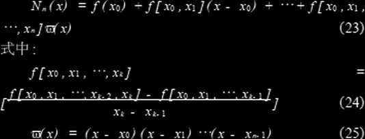
Newton interpolation formula
Interpolant order grows with node count: two nodes give linear, three give parabolic interpolation; higher orders introduce spurious inflections and amplify data-error propagation. The implementation therefore uses a three-point rolling Newton interpolation — a modified piecewise scheme that markedly improves accuracy at modest additional computation.
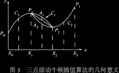
Fig. 3 Geometric meaning of the three-point rolling Newton interpolation (P0–P3 sample points, C0–C2 interpolation nodes)
With P0–P3 the given sample points and C0–C2 the interpolation nodes: between P0 and P1 the function is built from Pn, P1, P2 to fix C0; between P2 and P3 from P1, P2, P3 to fix C2; intermediate nodes are the mean of two constructions. Sampled data (opening/time, torque), noted (T(i), U1(i)), i = 0…N−1, is interpolated, converted to decimal and displayed. A verification routine allows a 1–5 N·m manual error after torque calibration before samples are accepted as accurate.
To verify sampling accuracy, the raw and interpolated low-bit fluctuation was tested: using the bridge principle of the strain sensor, a signal-generator circuit (1.5V battery, two high-precision potentiometers in parallel, each in series with a precision resistor) supplied a 0–20mV analog signal to the sampling circuit with common ground.

Fig. 4 0–20mV signal generator circuit
Varying the potentiometers produced 0–20mV signals; (max − min)/range of the measured values gave a sampling accuracy of 2.5‰ — sufficient for dynamic torque measurement of electric actuators.
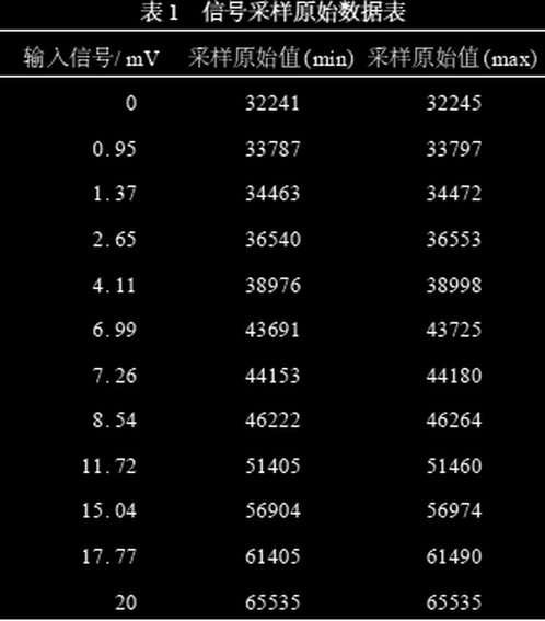
Table 1 Raw sampling data
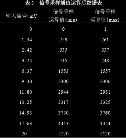
Table 2 Data after interpolation
Field accuracy was verified by calibrating the lower computer with a high-precision torque calibrator: assuming ideal sensor linearity, five points were calibrated in each rotation direction and intermediate values linearly interpolated. Tests also confirmed the sensor output is not perfectly linear — more calibration points yield higher accuracy; where resources allow, look-up tables should be used for torque values.
With calibration complete, dynamic-torque tests were run on electric actuators; Table 3 lists repeated-torque deviation data (related to sensor linearity, calibration accuracy, loading curve and the actuator's own repeatability). Multiple tests across actuator models confirmed stable system accuracy meeting torque-measurement requirements.
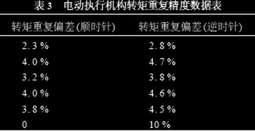
Table 3 Repeated torque deviation data measured by the lower computer
Nonlinear dynamic-torque variation caused by the loading mechanism, sensors and human factors demands high measurement speed and accuracy. Real-time sampling with a high-speed sensor and high-resolution ADC, optimized by three-point rolling Newton interpolation, met the accuracy requirements in practice and improved measurement reliability, providing dependable quality assurance for electric-actuator testing.
[1] Wang Henghai. LabVIEW-based temperature measurement and control system design. Instrument Technique and Sensor, 2007(4). [2] Zhang Jinlong et al. Ultra-precision angular displacement measurement and control. Journal of Scientific Instrument, 2006, 27(12). [3] Wu Yihua et al. Comparison of ADC clock-jitter sampling methods. Journal of Electronic Measurement and Instrument, 2007, 21(2). [4] Gao Changyin et al. Dynamic characteristics of a new piezoelectric torque sensor. Journal of Scientific Instrument, 2006, 27(8). [5] He Ping et al. RBF-network model for pressure-sensor temperature-drift compensation. Journal of Scientific Instrument, 2008, 29(3). [6] Li Kun et al. A low-cost static-parameter test method for ADCs. Journal of Scientific Instrument, 2006, 27(12). [7] Liu Dawei, Lu Changhua. Status of mixed-signal circuit fault diagnosis. Foreign Electronic Measurement Technology, 2007, 26(11). [8] Pielorza. Vibration problems in selected torsional mechanical systems. Meccanica, 2003, 38.
Compiled from a Chinese academic paper (ocpv.net article library); equations and test data reproduced from the original. Need electric actuators sized and supplied? Submit an RFQ.

An industry resource for electric & pneumatic actuators, dampers and heaters: brand manuals, sizing guides and maintenance know-how. Global brands in, China manufacturing out.