Electric actuators are indispensable electromechanical devices in process-control automation. This primer — covering construction, standards, the three main types, control functions, valve operating characteristics and selection points — was compiled from a Chinese WeChat technical column; figures are reproduced in their original order.
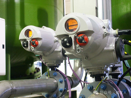
Electric actuators are indispensable electromechanical devices in process-control automation. Powered by electricity, they precisely receive analog or digital signals from the control system and convert them into corresponding rotary or linear mechanical displacement, achieving precise control of various valves (control valves, on-off valves, gate valves, plug valves, etc.) and automatic regulation of controlled variables such as pressure, flow, temperature and level.
A typical electric actuator consists of the electric motor, gear-train reducer, stroke-limiting mechanism, torque-limiting mechanism, position feedback mechanism, manual/electric changeover mechanism, manual operation mechanism (handwheel) and control unit, all working together for stable, reliable operation.
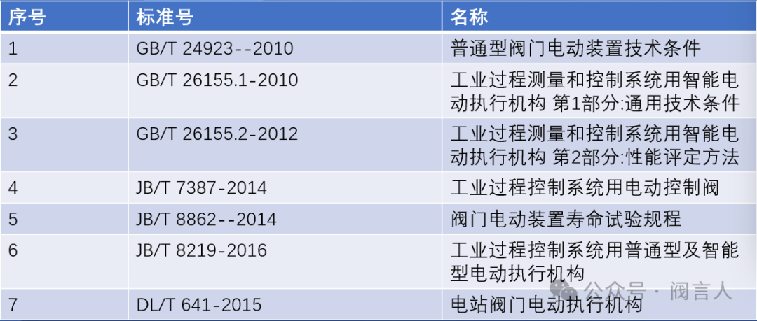
The industry standards commonly applicable to electric actuators are as follows:
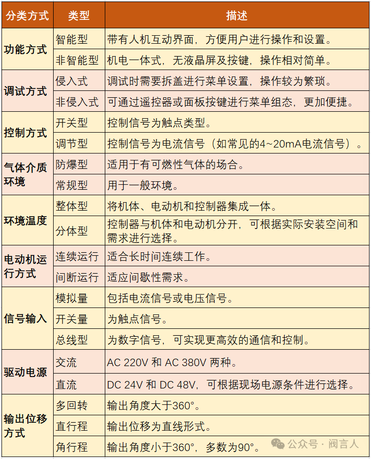
Electric actuators are complex and costly, and lack the intrinsic safety of pneumatic actuators; in hazardous locations, explosion-proof and other safety measures must be considered. By the relation between output displacement and input signal they divide into integrating type (output displacement proportional to the time integral of the input signal) and proportional type (output displacement proportional to the input signal). Common classifications:
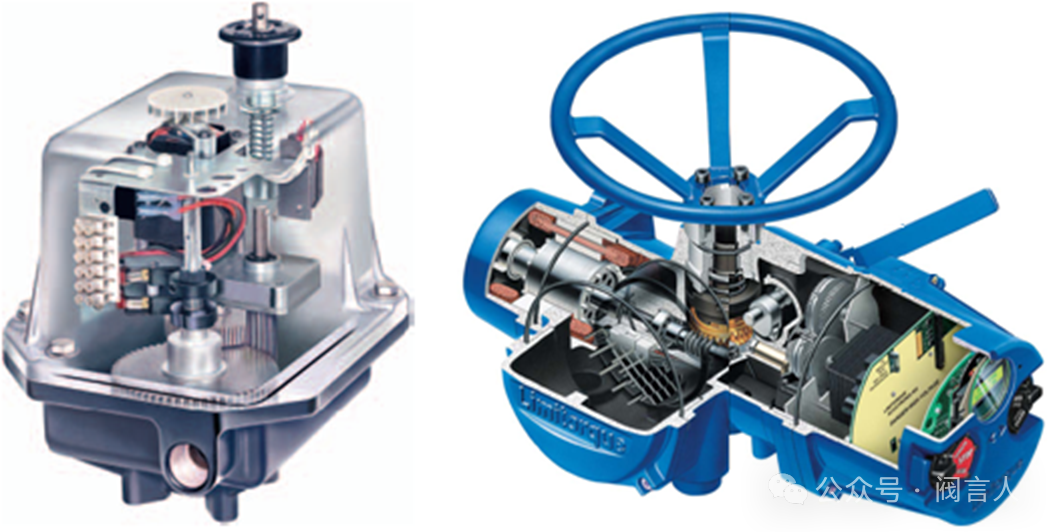
The working framework diagram of an electric control valve: the stroke-limiting mechanism constrains actuator travel — when the valve reaches the set position the limit switch trips and the motor stops; the travel is set by adjusting the cam position.
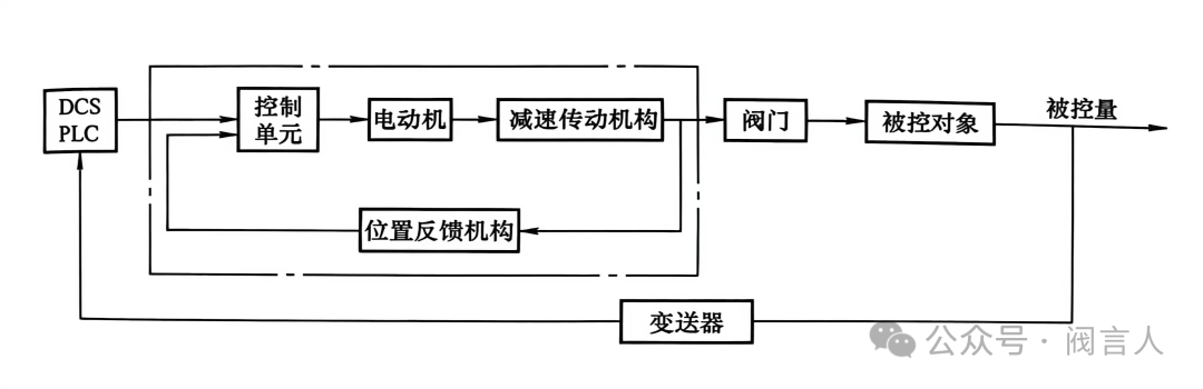
Working framework diagram of an electric control valve
The torque-limiting mechanism keeps the motor working within a safe torque range: when output torque exceeds the set limit, deflection of the gears under load trips the torque switch and stops the motor; compressing or releasing the torque spring adjusts the limit value.
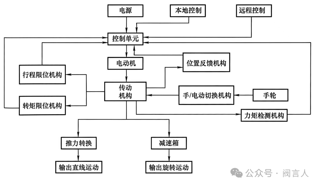
Electric actuator construction block diagram
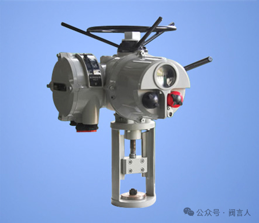
A linear-stroke actuator is built on a multi-turn base by adding a trapezoidal screw-nut drive, mounting bracket and travel-adjustment mechanism, converting multi-turn torque and speed into linear stroke and thrust for rising-stem valves (single- and double-seat control valves). In another arrangement the mechanical drive rotates the screw directly and the nut sleeve outputs the linear displacement.
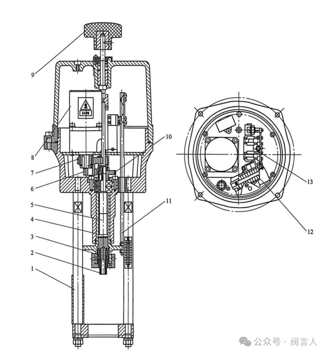
Linear-stroke actuator construction: 1 bracket rod; 2 stem connector; 3 disc springs; 4 nut sleeve; 5 screw; 6 double gear; 7 motor gear; 8 motor assembly; 9 handwheel assembly; 10 large-gear assembly; 11 feedback assembly; 12 control assembly; 13 stroke-limiting mechanism
Key technical parameters: operating temperature, ambient temperature, duty rating, basic error, hysteresis and deadband. Main performance parameters include thrust, power supply, speed, power consumption, weight and handwheel mounting.
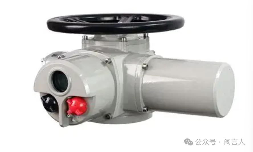
A quarter-turn actuator is a multi-turn base with a worm gearbox, typically outputting 90° rotation for butterfly, ball and plug valves. By mounting interface there are two kinds: direct-mounted (output shaft coupled directly to the valve stem) and base-and-crank (connected via a crank).
Technical parameters are similar to the linear type; main performance parameters include torque, power supply, speed, power consumption, weight and handwheel mounting.
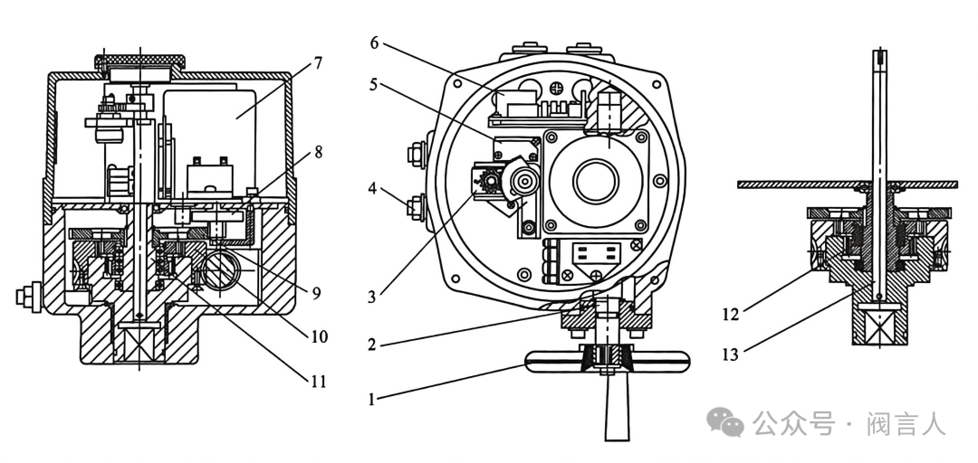
Quarter-turn actuator construction: 1 handwheel; 2 rod; 3 counter member; 4 limit member; 5 limiting mechanism; 6 control member; 7 motor assembly; 8 idler-gear assembly; 9 large gear; 10 worm wheel; 11 planetary-gear assembly; 12 drive assembly; 13 feedback rod
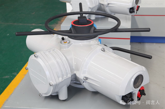
A multi-turn actuator is driven by a single- or three-phase motor through a worm-gear reducer. The gearbox contains a manual/electric changeover: with the lever in manual, the handwheel drives the output shaft through a clutch; under electric operation the changeover drops back automatically, the clutch engages the worm wheel and the motor drives the shaft. A torque sensor on the motor worm shaft and a position sensor driven via bevel gears provide precise position and torque control.
Technical parameters again include operating/ambient temperature, duty rating, basic error, hysteresis and deadband; main performance parameters include output speed, rated speed, motor power consumption, rated current and flange form.
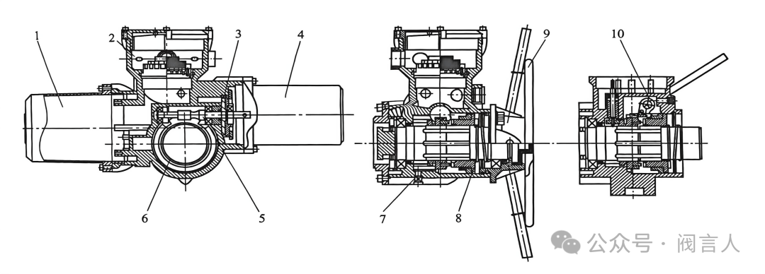
Multi-turn actuator construction: 1 control assembly; 2 junction-box assembly; 3 control assembly; 4 motor assembly; 5 worm assembly; 6 worm-wheel assembly; 7 position feedback mechanism; 8 clutch return spring; 9 handwheel; 10 manual/electric changeover
1. Overall control: local control via field pushbuttons, or remote control receiving commands from the control system for automatic, centralized operation.
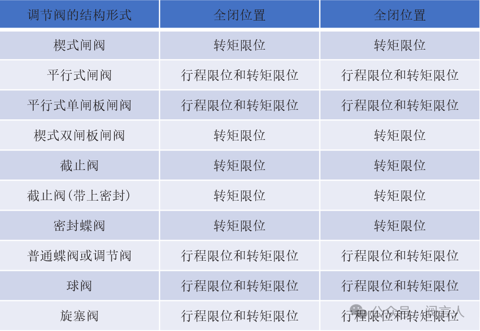
2. Limiting methods: stroke limiting, torque limiting, or combined stroke-and-torque — selected according to valve type for safe, reliable operation.
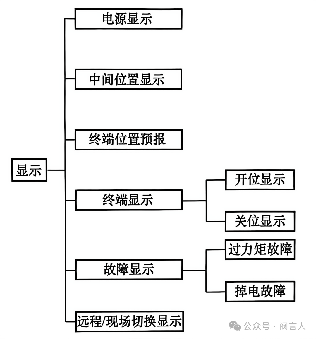
3. Display: an LCD shows running status and fault alarms in real time, helping field inspectors catch problems early.
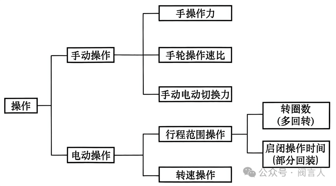
4. Operation modes: manual (handwheel) and electric (motor-driven); on electric operation the handwheel is automatically disengaged. Operating methods differ and must be applied correctly.
For a gate valve, the required operating torque rises sharply below 10% opening — throttling increases the pressure differential across the disc, demanding more stem torque. After closure, the static friction coefficient exceeds the dynamic one, so opening torque exceeds closing torque. The actuator must therefore deliver sufficient torque across all openings.
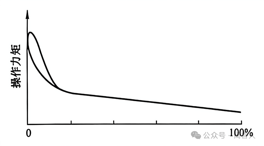
Linear (gate valve) actuator torque characteristic curve
A ball valve's torque curve is peak-shaped: at mid-opening the flow changes direction inside the ball, creating swirl that diminishes as the valve travels. The actuator must adjust its output promptly to keep the ball valve stable.
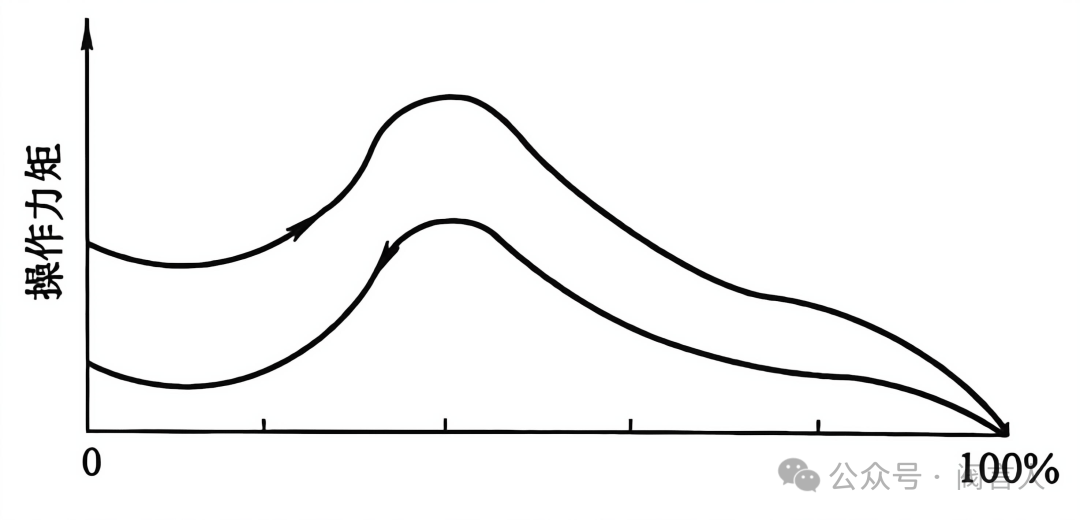
Ball valve torque characteristic (peak-shaped) curve
Electrical parameters: choose the drive power supply to match site conditions.
Output displacement: linear motion → linear-stroke actuator; rotation under 360° (ball/butterfly) → quarter-turn; rotation over 360° (gate valves) → multi-turn.
Hazardous environment: non-explosion-proof types for non-flammable-gas areas; explosion-proof types mandatory where flammable gases are present, with the rating matched to the gas group (e.g. d IIBT4, d IICT4).
Control mode: on-off valves take two-position actuators with contact-type signals; control valves take modulating actuators with 4–20mA signals.
Ambient temperature: above 70 °C choose a split (remote-electronics) actuator; below 70 °C an integrated one.
Force safety factors: for control valves the actuator output thrust should be 1.2× the valve's required thrust; for on-off valves 1.2–1.5× the required force, ensuring reliable travel without torque shortfall.
The original article presents common electric-actuator faults and remedies in two reference tables:
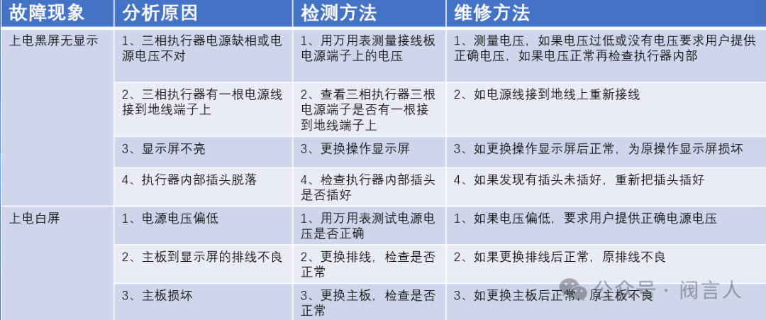
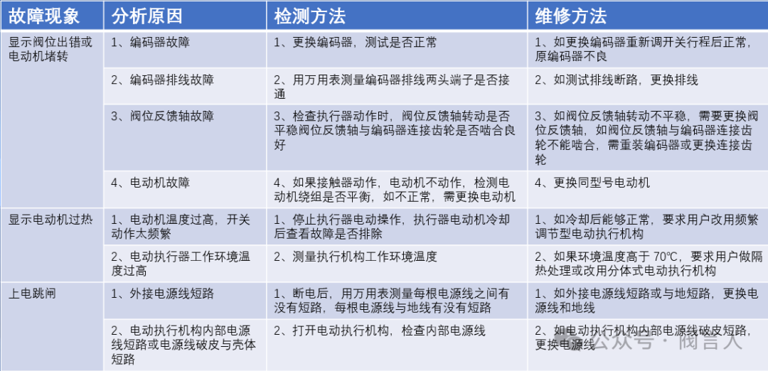
Compiled from a Chinese WeChat technical column; figures reproduced in original order. Need electric actuators sized and supplied? Submit an RFQ.

An industry resource for electric & pneumatic actuators, dampers and heaters: brand manuals, sizing guides and maintenance know-how. Global brands in, China manufacturing out.