What should an electric actuator look like in the fieldbus era? This design article offers a complete answer: an 89C52RC+ microcontroller as the control core, connected to the FOUNDATION Fieldbus (FF) through an FB3050 chip and MAU circuit, paired with a rare-earth permanent-magnet low-speed synchronous motor and a self-locking planetary reducer — with intelligent calibration (one key press at each end position), four categories of self-diagnostics, LCD opening display, and bumpless auto/manual switching. Note: this is an academic design concept (originally published around 2011 on China's ocpv.net control-valve article library) with no field test data; the scheme is presented for study. Figures 1-4 are from the original article.
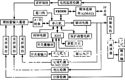
Figure 1. Block diagram of the bus-type intelligent electric actuator (original figure)
The actuator is the terminal device of an automatic control system, with a major impact on safe operation, reliability and control quality — yet it is the weakest link and the "bottleneck" of such systems. Imported actuators vary in approach and generally show a trade-off: highly reliable units are not necessarily sensitive or precise, and sensitive/precise ones are less reliable; moreover, foreign suppliers rarely transfer the core servo-controller technology, and if they do, at high prices. As control technology entered the fieldbus stage, conventional electric actuators fell far short of fieldbus device requirements. A bus-type intelligent electric actuator can both meet plant needs and satisfy fieldbus device requirements.
The actuator consists of a digital control section and an execution section. The control section is built around the 89C52RC+ MCU with advanced ICs: sensitivity, zero point and travel of the control valve can be preset, and valve position set by analog or digital input signals. The execution section — servo motor, reducer and position sensors — performs the mechanical action under the control section's command.
Current, voltage, temperature and position sensors feed drive-circuit output, motor temperature and shaft-position signals through A/D conversion into the MCU; the MCU communicates with the fieldbus via the FB3050 and MAU, and drives the servo motor forward/reverse through the drive circuit for speed and position control. The MAU circuit filters the bus signals and converts them to CMOS levels acceptable to the FB3050, converts FB3050 output into FF-protocol bus signals, and isolates the instrument from the FF bus through an isolation transformer.
The position sensor is a long-life differential transformer (LVDT): the travel-detection mechanism converts shaft mechanical displacement proportionally into an electrical signal for the controller, while also sending it to the control room for monitoring; two limit micro-switches ensure safe operation and two groups of contact outputs join the system control. For motor reliability and positioning stability the design uses a rare-earth permanent-magnet low-speed synchronous motor; the reducer is an efficient floating planetary gear stage with mechanical self-locking, converting motor rotation into large-torque angular displacement.
Controller outputs (P3.0, P3.5) command the servo motor's forward, reverse and stop states so the actuator position tracks the setpoint. The MCU outputs, through a logic interlock circuit, control two solid-state relays (KSSR1, KSSR2) that energize the motor's two coils — the interlock guarantees the two relays never close simultaneously, protecting the motor; the motor therefore has exactly three states: forward, reverse and stop.
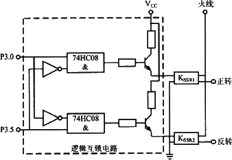
Figure 2. Drive circuit (original figure)
Solid-state relays prevent contact erosion, greatly extend contactor life, and eliminate phase-to-phase short-circuit risk. The base circuit comprises two boards — an instrument board and a communication board — linked by a serial interface. The instrument board handles sensor sampling/processing, A/D conversion, filtering, linearization (and D/A when analog output is fitted) plus the display, making the instrument intelligent; the communication board gives it communication capability, putting measured and control values onto the FF line.
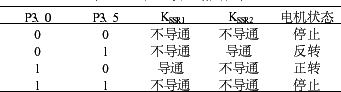
Table 1. Logic interlock truth table (original figure)
Digital communication lets the actuator retain additional information (process-related descriptions, ranges and units, maintenance activity records) and read it out on demand, enabling instrument asset management systems. With FF, the actuator gains further monitoring capabilities:
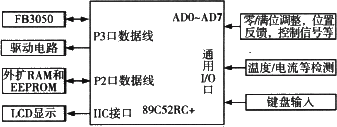
Figure 3. Controller structure diagram (original figure)
The controller is built from the 89C52RC+ MCU and its peripheral circuits, and performs:
Software is split into control, communication and management: the control part samples process variables, processes data and computes outputs; the communication part implements the FF data-link and application layers (the communication stack); the management program covers LED display, mode management, alarm indication, key scanning, power-fail protection, interrupt service routines and self-diagnostics. Functions include A/D sampling, data processing, linearization, zero/span checking, range conversion, self-diagnostics, configuration and the FF communication stack. The code is MCS-51 assembly, modularly designed; the main program flow is shown in Figure 4.
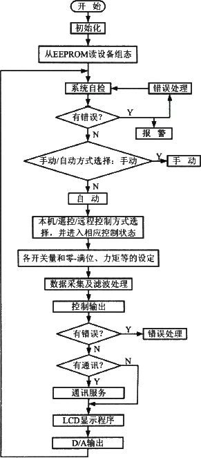
Figure 4. Main program flowchart (original figure)
The original article further predicted that as fieldbus technology matured and standards unified, fieldbus instruments would become the mainstream: FF interoperability allows multi-vendor instruments on the same bus, with like-for-like interchangeability — a broad market prospect.
Need bus-type or intelligent electric actuators sized and supplied? Submit an RFQ.

An industry resource for electric & pneumatic actuators, dampers and heaters: brand manuals, sizing guides and maintenance know-how. Global brands in, China manufacturing out.