In industrial automation systems, the AUMA electric actuator is core equipment for valve automation. Inaccurate limits, drifting feedback signals and nuisance torque trips are the most common commissioning pitfalls. This hands-on guide is designed for operations and instrumentation engineers to consult on site, stepping through the actuator's complete adjustment.
Bottom line: for AUMA actuator field setting, follow one sequence — mechanical limits → torque protection → analog feedback calibration. Key numbers: a 5 mm screwdriver for the limit adjusters, pointers step 90° per turn; torque dial unit 1 daNm = 10 Nm; calibration targets 0/4 mA at closed and 20 mA at open depending on the signal scheme (quick-reference table below). Torque protection is always active, does not self-reset after tripping, and must never be blindly increased.
Safety notes
- Observe the site electrical safety code when working on live equipment
- Torque settings must follow the valve manufacturer's factory data — never increase torque arbitrarily; confirm any change with the valve manufacturer
- This article is a technical primer; on site, the manufacturer's official manual and project drawings always take precedence
1. Limit Switch Setting (Core Position Adjustment)
Basis for this procedure: clockwise output rotation = valve closing. Limits are split into the closing direction (black zone) and opening direction (white zone).
| Direction | Zone | Adjuster / pointer / mark | How to |
|---|
| Close limit | Black | Press adjuster A, rotate along the arrow; watch pointer B to mark C | Handwheel to full closed; pointer steps 90° per turn — slow down within the last 90°, align with C, release; overshoot can be corrected by continuing in the same direction |
| Open limit | White | Press adjuster D, rotate along the arrow; watch pointer E to mark F | Handwheel to full open then back 1/2 turn; pointer steps 90° — approach F slowly, align, release |
1.1 Closing-direction limit
- Turn the handwheel to wind the valve fully closed
- With a 5 mm screwdriver, press adjuster A and rotate in the arrow direction; you will hear the gears mesh, and pointer B moves 90° per step
- When pointer B is within 90° of marker C, slow down; release the screwdriver once the pointer aligns precisely with marker C. If you overshoot, keep rotating in the same direction until aligned
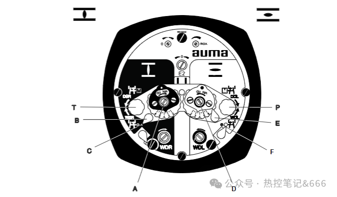
1.2 Opening-direction limit
- Wind the valve counter-clockwise to fully open, then back off 1/2 turn
- Press adjuster D with the 5 mm screwdriver and rotate in the arrow direction, watching pointer E, which also steps 90°
- As pointer E approaches marker F (within 90°), adjust slowly; release once aligned. Overshoot can be corrected by continuing in the same direction
💡 Handy tool: the red test buttons T and P on the panel are used specifically to verify the torque switch and position limit switches.
2. DUO Intermediate Position Switches [Optional]
Key characteristic: the intermediate switches actuate only when the valve is electrically operated in the same direction; two intermediate start/stop points are freely definable, using NO/NC contacts to stop the valve mid-travel.
- Wind the valve manually to the desired intermediate position
- Closing-direction intermediate point (black zone): press adjuster G and rotate, watching pointer H; approach marker C slowly and release the screwdriver once aligned
- Opening-direction intermediate point (white zone): press adjuster K and rotate, watching pointer L; approach marker F slowly and release once aligned
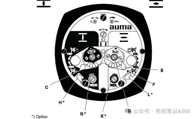
3. Torque Switch Setting | Key Overload Protection
Torque protection is the valve's most important safeguard — excessive torque can destroy the valve.
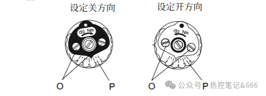
- Loosen the torque dial locking screw O
- Rotate the torque dial P to the target torque
- Unit conversion: 1 daNm = 10 Nm, e.g. 3.5 daNm = 35 Nm. Opening and closing torques are set separately
- When confirmed, retighten screw O
📌 Key points:
- Torque protection remains active throughout — even at the travel end positions, an overload still trips
- Torque protection does not reset automatically after tripping
- The torque switch also protects while the valve is handwheeled
4. Complete Test Run
After all mechanical adjustments, always perform a powered test run!
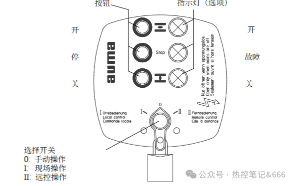
- Set the selector switch to OFF and energize the actuator
- Handwheel the valve full open and full closed; if the limit stop positions are off, return to the limit-setting step
- Once correct, set the selector to LOCAL and test open-stop-close with the panel buttons
- Press the red test buttons T and P to recheck the torque and limit switch actions
Note: with the selector at OFF, external remote control inputs are not interrupted.
5. Mechanical Position Indicator [Optional]
The indicator turns about 180° over the full stroke; changing the valve stroke requires changing the internal reduction gears.
- Wind the valve fully closed and rotate the lower (closed-symbol) indicator disc until the mark aligns with the housing mark
- Holding the lower disc, wind the valve fully open and rotate the upper (open-symbol) disc until its symbol aligns
6. Potentiometer Zero and Span
The potentiometer provides the base resistance signal for remote position transmission.
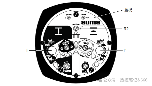
- Place the valve fully closed by hand; remove the switch-compartment cover (remove the indicator disc first on models fitted with one)
- Rotate the main potentiometer R2 clockwise to its end stop — corresponding to 0% (fully closed) and 100% (fully open) valve position
- Adjust the additional zero-trim potentiometer to compensate resistance deviation from the reduction gearing
- Refit the indicator disc; check the seals and O-rings, lightly grease the sealing faces, and refasten the compartment cover
7. RWG Position Feedback Transmitter Calibration (4–20 mA / 0–20 mA)
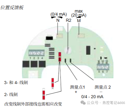
Transmitters are factory-preconfigured, but after installation you must verify the output current against the actual valve position and recalibrate if deviant.
7.1 2-wire 4–20 mA, 3-/4-wire 4–20 mA calibration
Calibration targets at a glance:
| Signal scheme | Closed target | Open target | Notes |
|---|
| 2-wire 4–20 mA | ≈4 mA (zero trim N) | 20 mA (span trim M) | R2 clockwise to its stop; the external load loop must be connected (terminals may be jumpered) or the current cannot be read |
| 3-/4-wire 4–20 mA | ≈0 mA (N) | 20 mA (M) | Run the full stroke repeatedly and recheck zero and span |
| Converting 0–20 mA to 4–20 mA | Three steps: 0.1 mA (N) → 16 mA (M) → raise to 4 mA with R2 | Recheck | Return to full closed for the R2 step; restore all covers afterwards |
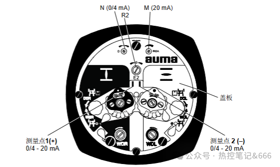
- Energize the actuator with the valve fully closed; remove the cover and connect a 0–20 mA ammeter to the test points
- ⚠️ The external load circuit must be connected — terminals may be jumpered — otherwise the current cannot be read!
- Rotate R2 clockwise to its limit and adjust the zero-trim potentiometer N. Fully-closed output: 3-/4-wire ≈ 0 mA; 2-wire ≈ 4 mA
- Run the valve to fully open and adjust the span trim M to calibrate the output to 20 mA
- Stroke the valve through several complete cycles, recheck zero and span, repeat if deviant, then refit all covers
❗ If the output cannot reach full span, check that the internal counting reduction gears match the actual valve stroke.
7.2 Converting 3-/4-wire 0–20 mA to 4–20 mA
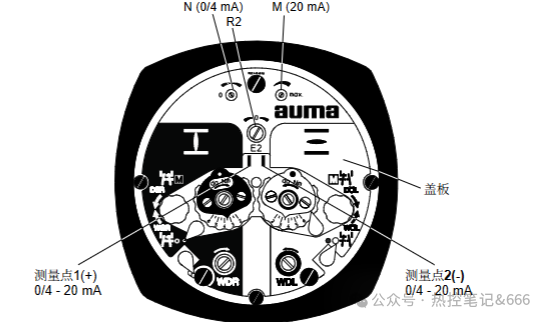
- Valve fully closed with the ammeter connected: adjust N to set the base zero to 0.1 mA
- Valve fully open: adjust M to output 16 mA
- Return the valve to fully closed and rotate R2 to raise the output to 4 mA
- Verify zero and span over complete strokes, then refit covers and end caps
💡 Reversing tip: if the feedback direction is inverted, swap wires 7 (red, RD) and 5 (black, BK) on the feedback board.
Field Commissioning Takeaways
Remember the order: mechanical limit setting → torque protection → analog feedback calibration.
- Torque protection shields the valve itself — never blindly increase torque
- For 4–20 mA commissioning, stroke the valve several full cycles to eliminate zero drift
- After all adjustments, refit every cover and maintain compartment sealing against moisture and dust
Disclaimer: this article is a technical primer for operations reference; on site, always follow the manufacturer's manual and project drawings.
Related reading: AUMA SA/SAR Series: Wiring, Limit & Torque Setting and Feedback Calibration; Universal Electric Actuator Wiring & Commissioning Guide; see also the AUMA brand column.