Reliable stroking of a pneumatic actuator depends on five accessory groups: the filter-regulator that cleans and regulates the air supply, the solenoid valve that switches and reverses the air path, the limit switch that feeds back valve position and interlocks, the positioner that builds a one-to-one correspondence between stem position and the control signal, and the hand-wheel mechanism as the manual backup during failures. This illustrated guide explains each accessory in turn: the solenoid section covers two-position two-way / three-way / four-way / five-way types with structure and motion diagrams, and the positioner section gives the full ABB TZID-C operating panel, operating modes, parameter groups and auto-tune procedures. The English view provides the abstract and bilingual section headings; slide figures are shared with the Chinese view.
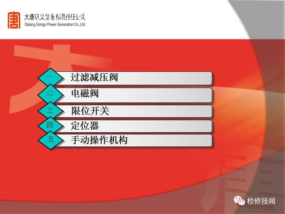
The five accessory groups: filter-regulator, solenoid valve, limit switch, positioner, manual mechanism
The filter-regulator is the first stage between the air supply and the actuator. A two-piece set (filter + regulator) filters and reduces instrument air pressure; a three-piece set (filter + regulator + oil-mist lubricator, gauge optional) additionally lubricates the air.
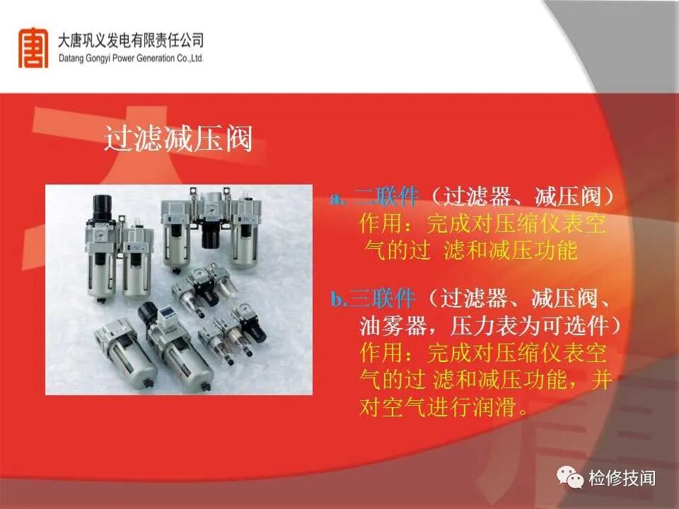
Two-piece and three-piece filter-regulator sets
An integrated filter-regulator removes particulates and dust; its graphical symbols are shown below. The purpose of the air filter: dirty air on the primary side passes through the filter element and leaves the secondary side clean, with moisture and particles separated into the bowl.
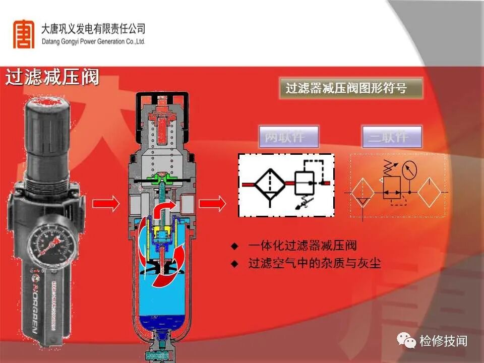
Filter-regulator cutaway and graphical symbols
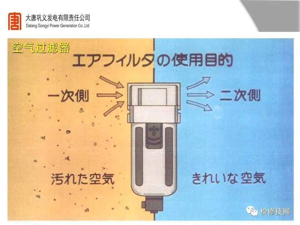
Air filter: primary side in, clean air out on the secondary side
Where a regulator is used: to reduce pressure and hold it steady — the supply pressure is stabilized at the actuator's working pressure downstream of the regulator.
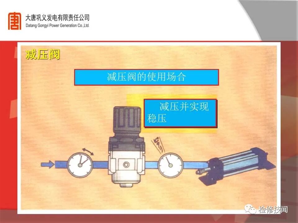
Regulator duty: reduce and stabilize pressure
Regulator structure: setting spring, diaphragm, relief orifice, feedback orifice and main valve spool; P1 is inlet pressure, P2 outlet.
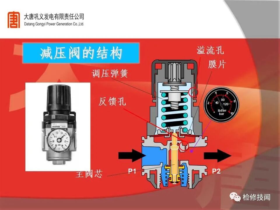
Regulator structure: spring / diaphragm / relief orifice / feedback orifice / main spool
How a regulator works: pull the setting knob up before adjusting so it can rotate; turning the knob clockwise raises P2; the spring force opens the main spool; P2 rises until it balances the spring force and holds; push the knob down to lock the setting.
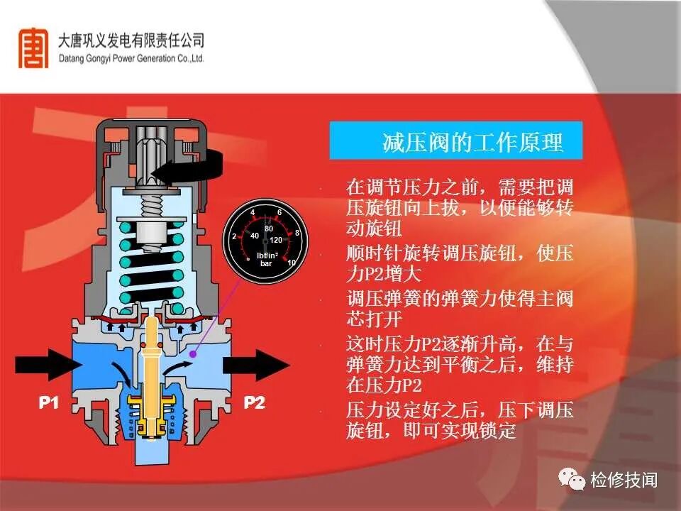
Regulator working principle, step by step
The solenoid valve sits between the positioner (or cylinder) and the air supply; energizing or de-energizing its coil switches the air path and determines the actuator's motion. The complete chain: pneumatic actuator + solenoid valve + valve.
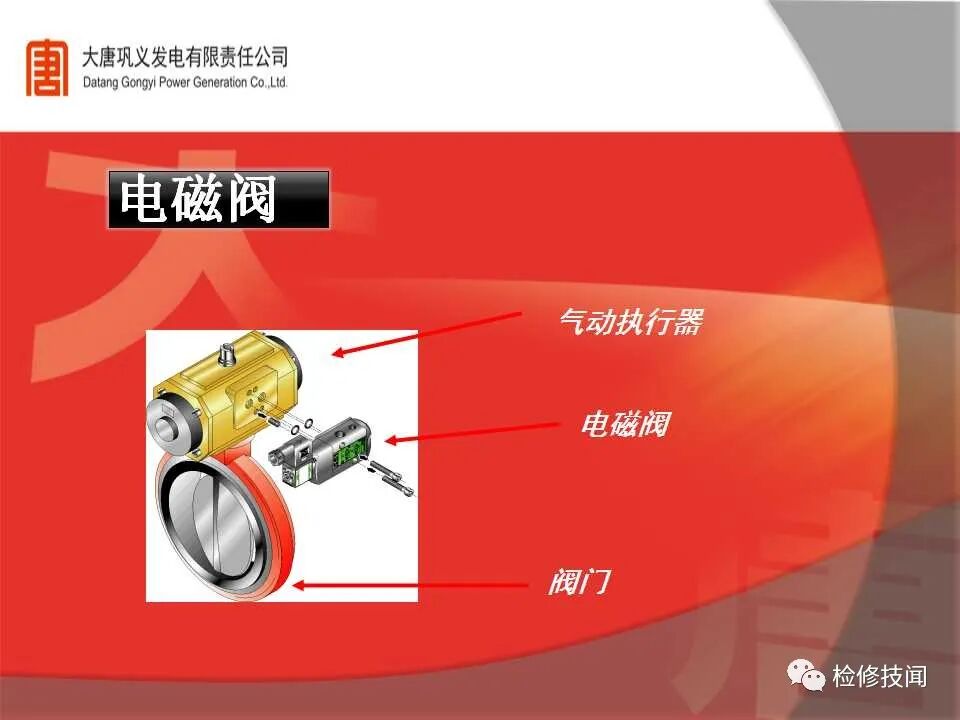
Actuator, solenoid valve and valve assembly
Classification (by common usage): two-position two-way, two-position three-way, two-position four-way, two-position five-way, and three-position five-way solenoid valves.
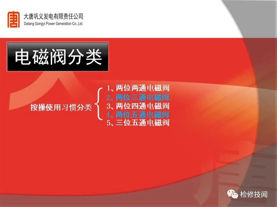
Solenoid valve classification
Two-position two-way: with the coil energized the armature moves the spool and connects P (supply) to A (outlet); de-energized, the spring returns and P-A closes.
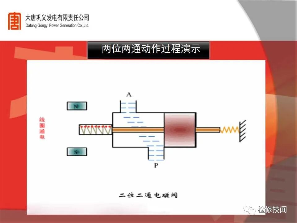
Two-position two-way motion (coil energized)
Two-position three-way: one supply port, one outlet port feeding the device, and one exhaust port (usually with a silencer). NC (normally closed) types open the path when energized and close it when de-energized — "jog" action; NO (normally open) types close the path when energized and open it when de-energized.
On site the three-way type dominates, widely applied to drain valves: an NC solenoid is chosen so that on loss of power or air the drain valve opens automatically by its internal spring, protecting the turbine from water ingress.
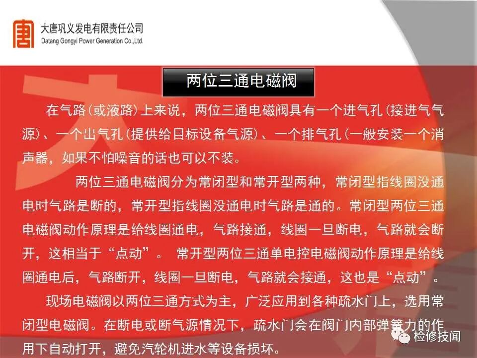
Two-position three-way: NC and NO behavior
Two-position three-way structure: direct-acting, 2-position single-coil — NC and NO versions, with the flow paths (P supply / A outlet / R exhaust) compared energized versus de-energized.
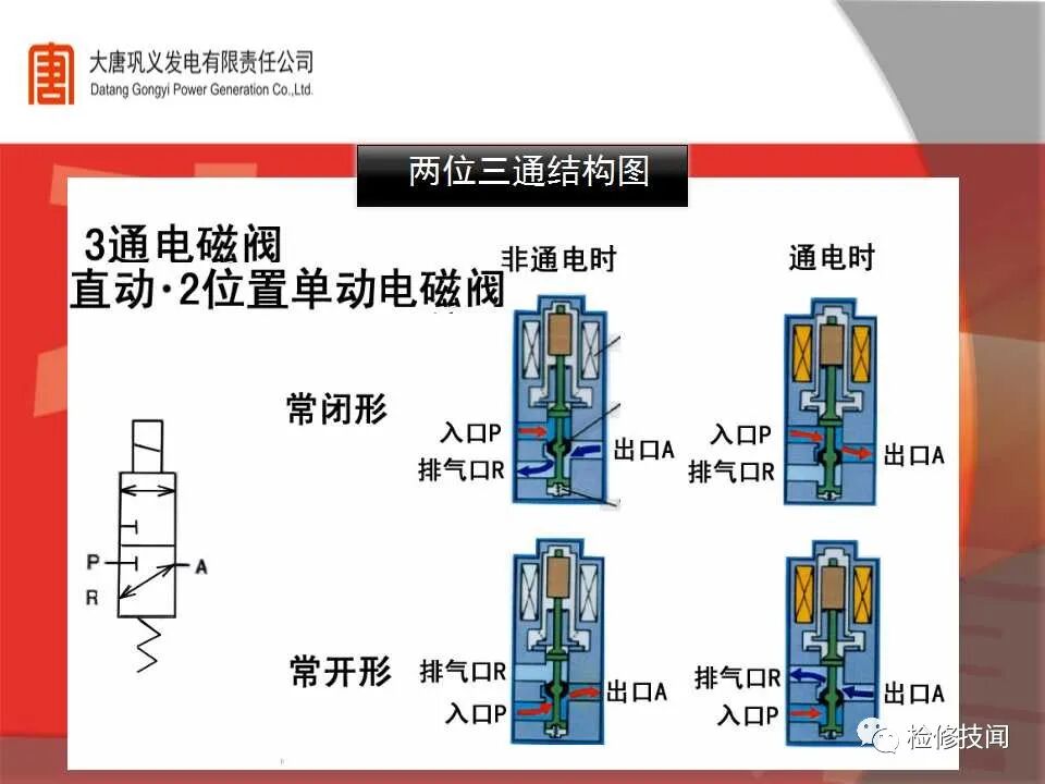
Two-position three-way structure: NC / NO, before and after energizing
Motion demo (cylinder type): de-energized — the spring-return actuator vents through the exhaust and holds by spring; energized — the coil shifts the valve, air flows in and the stem strokes.
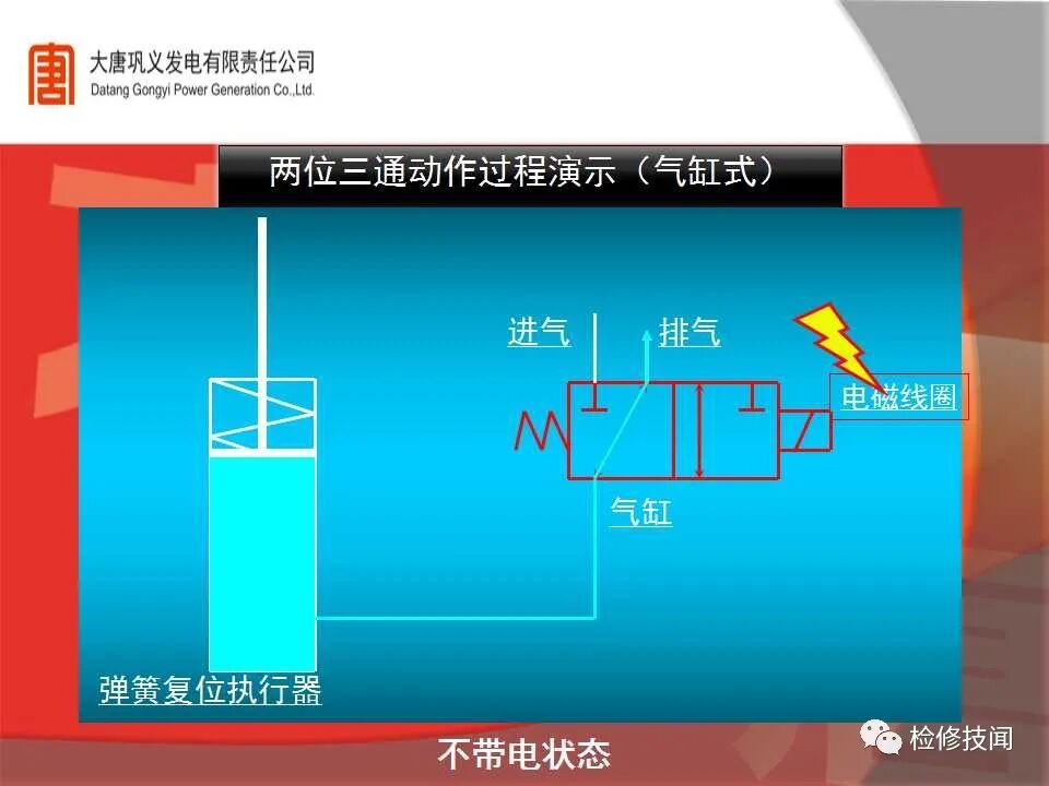
Two-position three-way demo (cylinder): de-energized
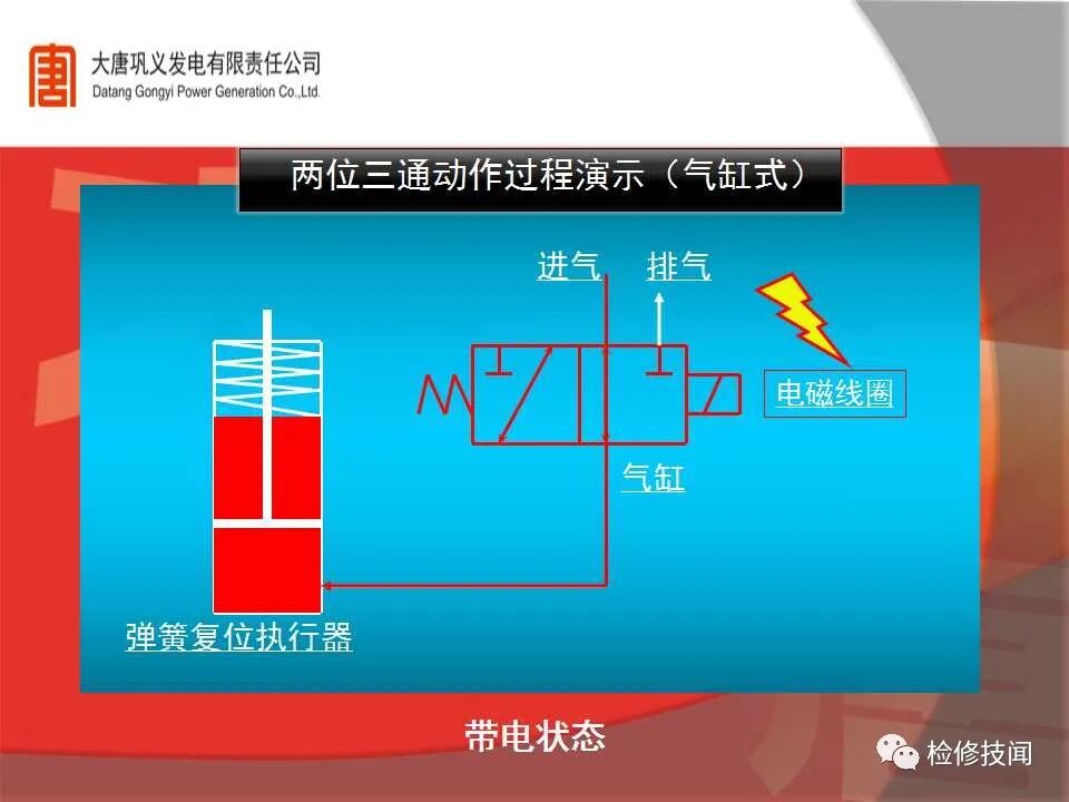
Two-position three-way demo (cylinder): energized
Two-position four-way: with the coil de-energized the spring holds the spool so ports A and B cross-connect to P and O, reversing a double-acting actuator.
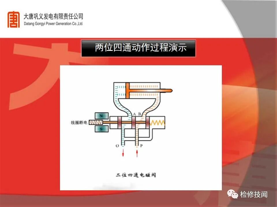
Two-position four-way motion (coil de-energized)
Two-position five-way: one supply port, one forward-action outlet and one reverse-action outlet (feeding the device's two directions), plus a forward and a reverse exhaust port (with silencers).
A double-coil five-way valve is self-locking: energizing the forward coil connects the forward path and it stays connected after de-energizing — until the reverse coil is energized; and vice versa. Thanks to this memory, control circuits and PLC programs need only pulse the coil for 1–2 seconds, protecting the coil from burnout.
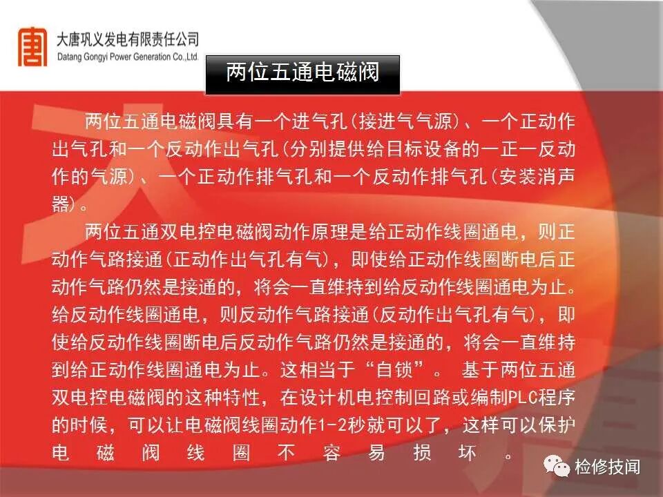
Two-position five-way: the self-locking (memory) feature
Two-position five-way structure: direct-acting, 2-position, coils on both sides — spool positions and flow paths (P, R, A, B) compared for A-side ON, neutral (after B-side ON) and B-side ON.
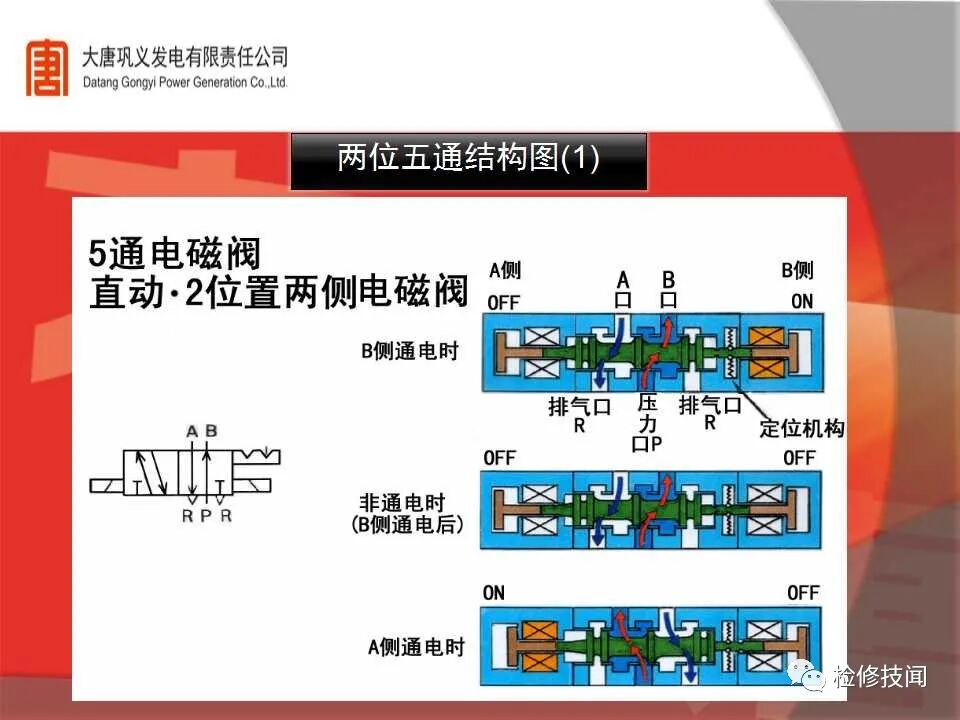
Two-position five-way structure: three spool states
Motion demo (cylinder type): the reversing of supply and exhaust to a double-acting actuator, de-energized versus energized.
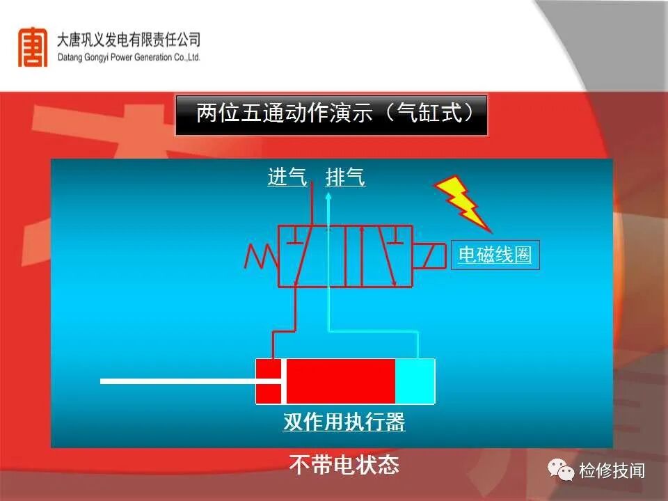
Two-position five-way demo (cylinder): de-energized
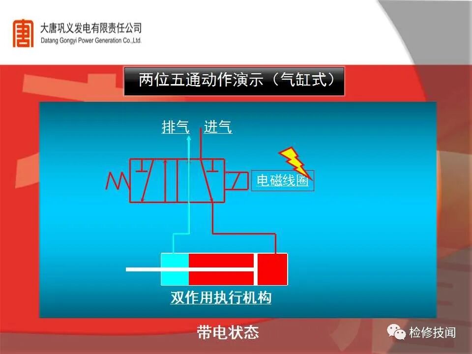
Two-position five-way demo (cylinder): energized
A limit switch (travel switch) is a low-current pilot device: the moving parts of the machine strike its actuator to open or close control circuits for indication and interlocking. On pneumatic actuators it converts full-open / full-close (or intermediate) positions into discrete signals for the control system.
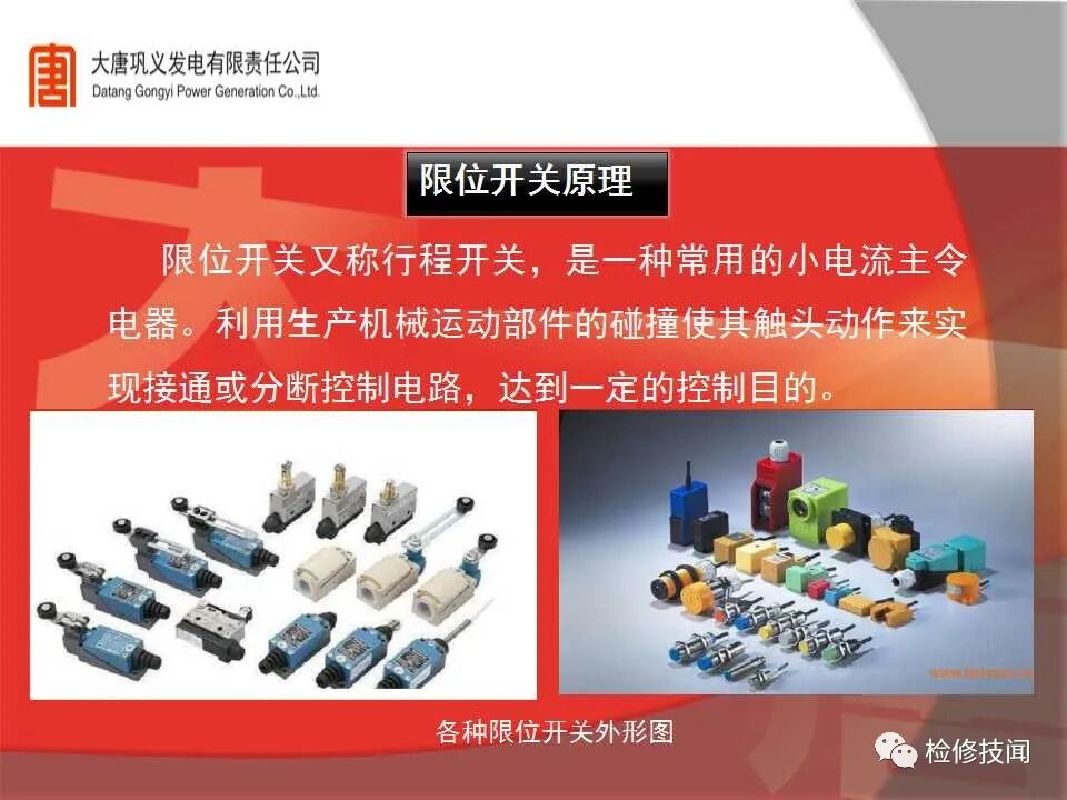
Limit switch principle and typical outline drawings
Principle: the valve positioner is the main accessory of a control valve. It takes the stem displacement as the feedback measurement, the controller output as the setpoint, compares the two, and adjusts its output to the actuator when a deviation exists — building a one-to-one correspondence between stem position and controller output. It is thus a feedback control system measured by stem position, with the controller output as setpoint and the positioner's output to the actuator as the manipulated variable.
Positioner principle: feedback vs setpoint comparison
ABB TZIDC operating panel: ENTER confirm key, up/down arrow keys, MODE key.
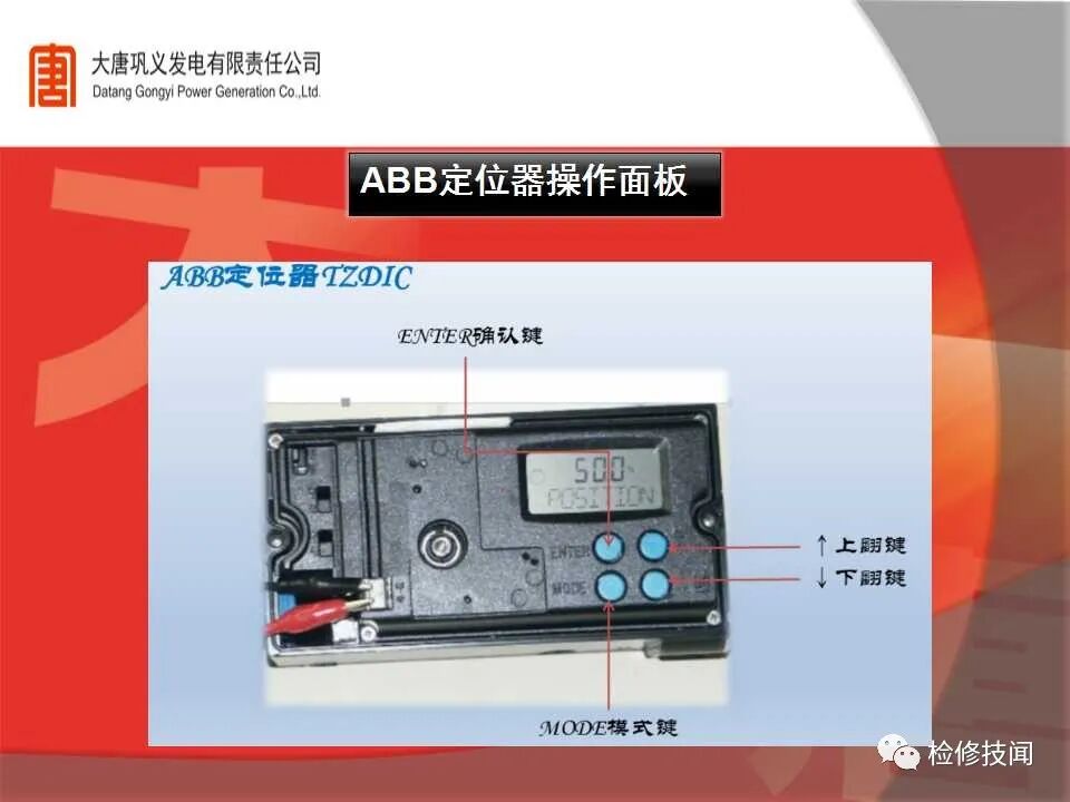
ABB TZIDC operating panel
Operating-level modes:
| Mode / display | Function |
|---|---|
| 1.0 CTRL-ADP | Adaptive control (remote) |
| 1.1 CTRL-FIX | Fixed control (remote) |
| 1.2 MANUAL | Local key operation (open/close) |
| 1.3 MAN-SENS | Check whether the travel range is suitable |
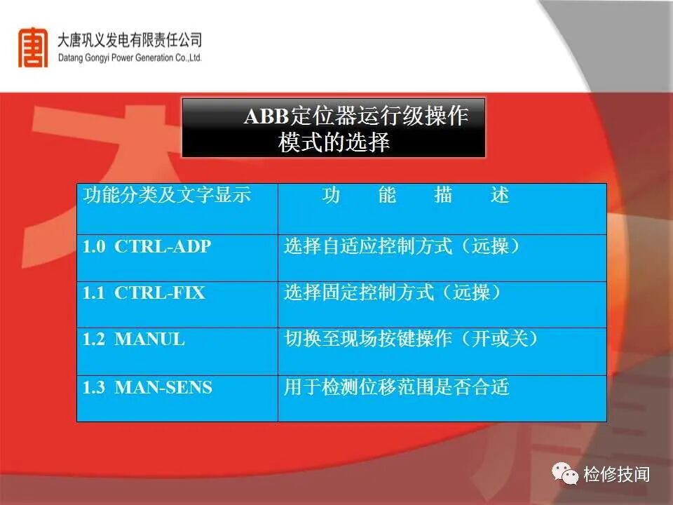
Operating-level mode list
Mode selection: normally select 1.0 for remote automatic control. Only when actual travel is very small and the actuator is fast — where control oscillates easily — select 1.1, at slightly lower accuracy. Modes 1.2 and 1.3 both drive the actuator from the keypad: 1.2 is for hand operation, 1.3 specifically checks whether the feedback lever's real travel exceeds the sensor's maximum range, so the lever linkage can be corrected for best control.
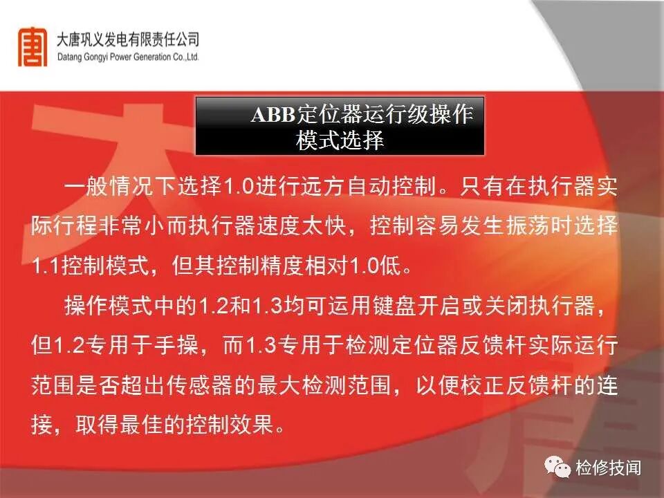
Mode selection notes
Configuration level: parameters are grouped P1._ through P11._ (P for PARAMETER), each group split into items — P1._ has P1.0–P1.5 (6 items), P2._ has P2.0–P2.8 (9 items). Some items offer sub-options: P1.0 selects LINEAR for angle transformation below 56° or ROTARY above 56°; P1.5 EXIT selects NV_SAVE (non-volatile save) to exit with saving, or CANCEL to exit without saving.
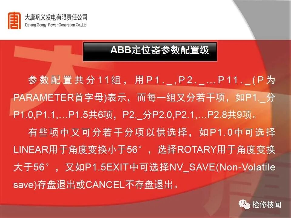
Configuration level: the 11 parameter groups
Parameter change example — direct to reverse action (the factory default suits a direct-acting valve; if the valve is reverse-acting — stem up to close — confirm P2.3=Reverse. Vendors usually preset this; it can be verified as follows). The starting mode can be any operating mode: press ↑ and ↓ together, tap ENTER, wait 3 s while the counter counts down from 3 to 0, release ↑/↓ — the display shows "P1.0 ACTUATOR".
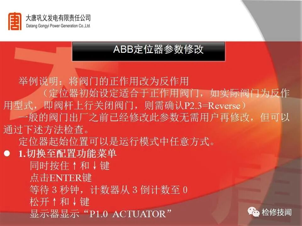
Parameter change example: entering the configuration menu
2. Select the second group: hold MODE and ENTER together, tap ↑ — "P2._ SETPOINT" appears; release both — "P2.0 MIN-PGE" appears. 3. Select the action parameter P2.3: hold MODE, tap ↑ three times — "P2.3 ACTION" appears; release MODE. 4. Change the action: tap ↑ or ↓ to select "REVERSE". 5. Exit via "P2.8 EXIT" with saving: hold MODE, tap ↑/↓ until "P2.8 EXIT" appears, release MODE, select NV-SAVE with ↑/↓, hold ENTER until the countdown ends.
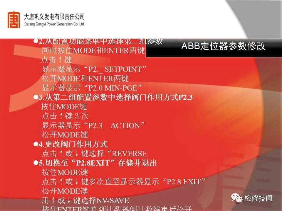
Parameter change (continued): group selection to save-and-exit
Which parameters matter: apart from P1.1, P2.3, P3.2 and P8.2, no others normally need changing. P1.1 is the auto-tune program; P2.3 the actuator action form (direct: output 1 pressure rises, stem goes down); P3.2 the direct/reverse control form (direct: 4 mA = 0% position); P8.2 the position-feedback form (direct: 0% position outputs 4 mA).
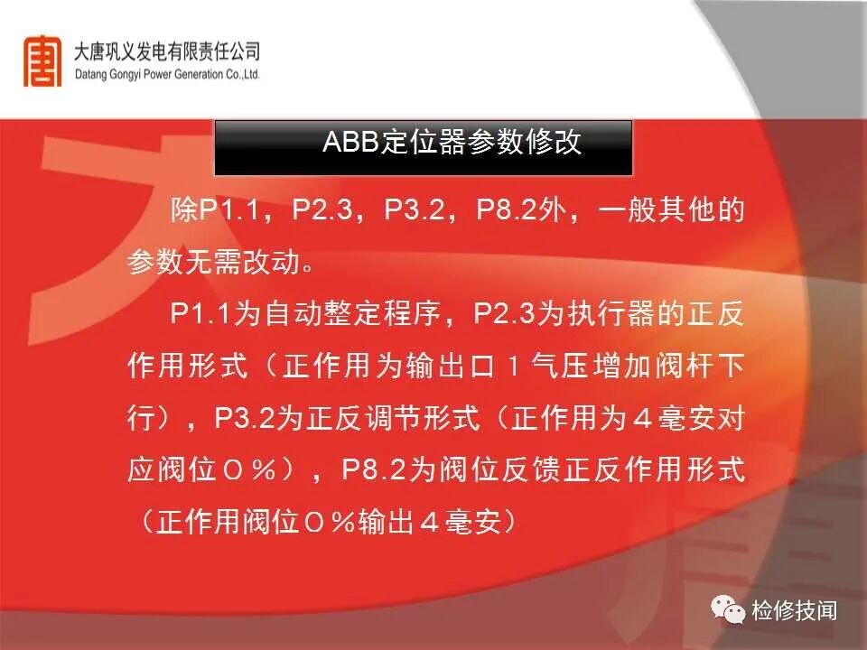
The four key parameters: P1.1 / P2.3 / P3.2 / P8.2
Auto-tune: hold MODE, tap ↑ until "P1.1" appears; release MODE; hold ENTER for 3 s until the counter reaches 0; release — the auto-tune program runs (showing the executing step number) and displays "COMPLETE" when done. If a fault occurs the program aborts with a fault code for diagnosis; it can also be interrupted manually. Optionally: "P1.2" adjust the control deviation band, "P1.3" the dead band, "P1.4" test the setting. Save: hold MODE, tap ↑/↓ to "P1.5", release, select NV_SAVE with ↑/↓ ("CANCEL" discards), hold ENTER for 3 s until the countdown ends (exit the configuration level this way even when discarding).
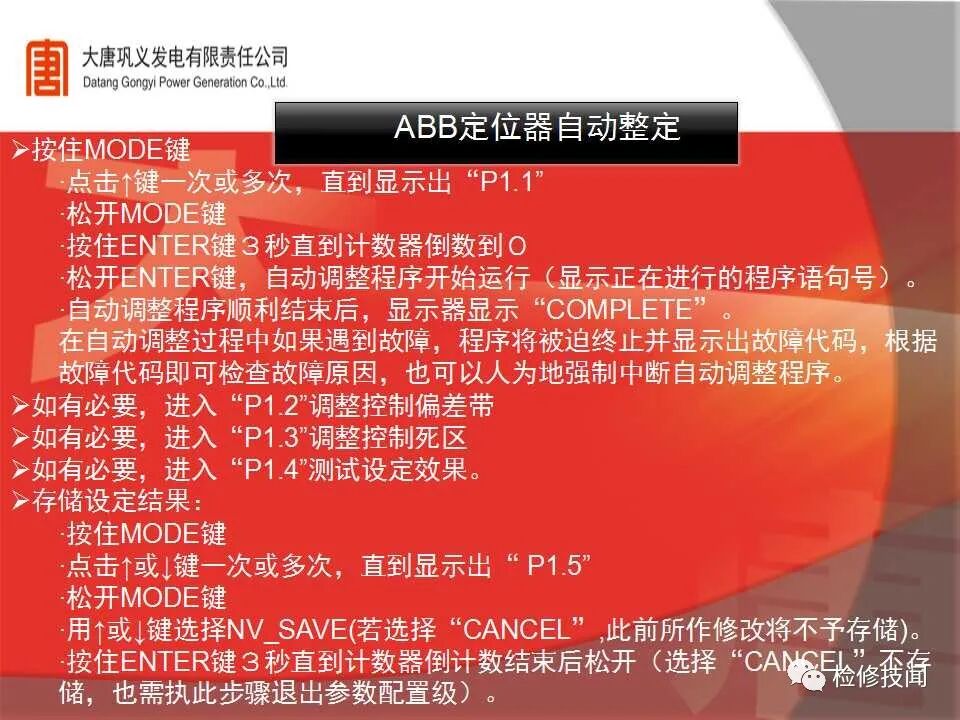
Auto-tune: P1.1 → COMPLETE → save at P1.5
Bus-type TZIDC auto-tune: hold MODE → display counts down 5, 4, 3, 2, 1 → press ↑ → release both after 3, 2, 1 → press MODE again to start auto-tune. When finished it returns to the initial screen automatically — no saving needed.
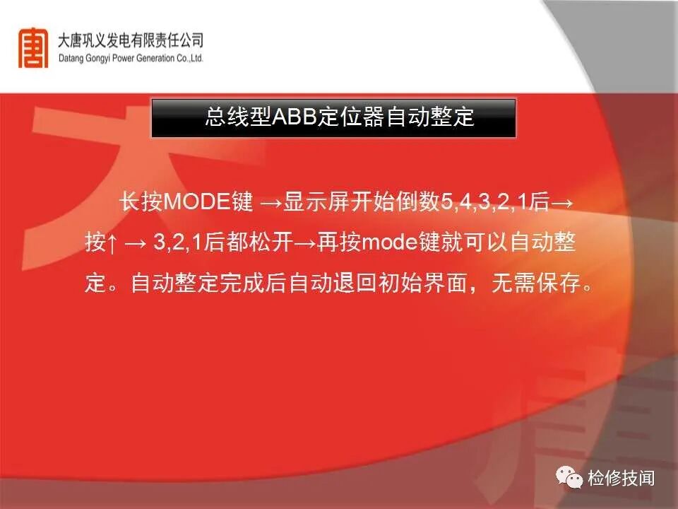
Bus-type auto-tune: key sequence
Manual mechanisms (handwheels / side levers) come in many forms, mounted directly on the actuator or via a bracket.
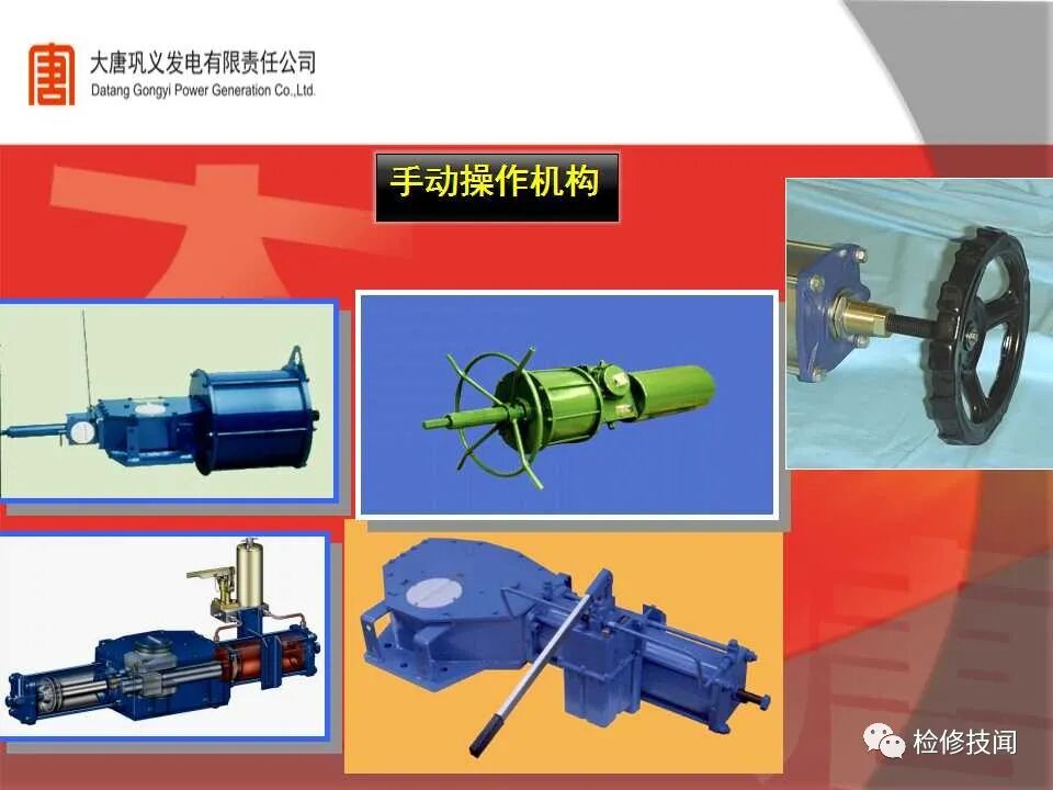
Typical manual operating mechanisms
Purpose of the handwheel: 1. to switch to manual operation when the control valve fails through diaphragm rupture, positioner malfunction, signal fault or air-supply failure — avoiding production loss or a safety incident; 2. to restrict the valve opening when the process forbids full open — the stroke can be limited by turning the handwheel.
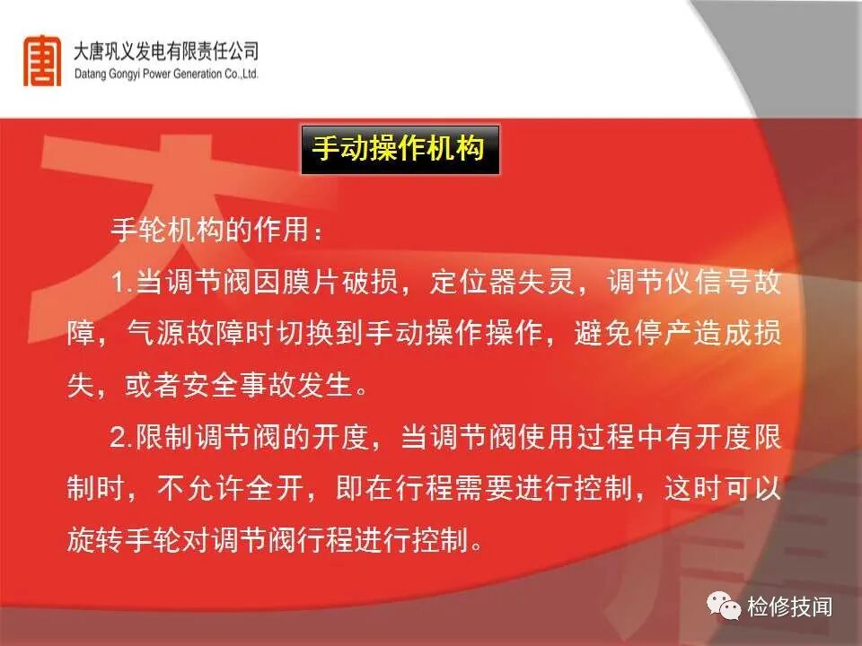
The two purposes of the handwheel mechanism
For complete supply of pneumatic actuators and their accessories — solenoid valves, limit switches, filter-regulators, handwheel mechanisms — and matched valve packages, submit your requirement via our RFQ form.
Pneumatic actuator O&M collection: air supply, accessories, testing and faults | DN800 butterfly valve in 3 seconds: the air-side scheme for fast-stroking large pneumatic valves | Siemens SIPART PS2 positioner: commissioning and troubleshooting | ABB TZID-C smart positioner: hands-on commissioning

An industry resource for electric & pneumatic actuators, dampers and heaters: brand manuals, sizing guides and maintenance know-how. Global brands in, China manufacturing out.