A control valve that starts oscillating after a positioner is fitted is one of the field's most common puzzles — the cause is usually not a broken positioner but gain matching in the cascade inner loop. This article merges two classic technical papers into one complete reference covering four questions: when a positioner is mandatory, its seven functions, why it can cause oscillation (and how smart types eliminate it), and smart positioner features/selection/common faults. Source: two technical discussions published on China's ocpv.net control-valve article library (circa 2011); Figures 1-2 are from the original (dark scans re-processed to white background).
1. When is a positioner mandatory? (7 cases)
- High friction with precise positioning required: high/low-temperature valves or valves with flexible graphite packing;
- Flow characteristic modification required;
- Wide controller proportional band but small-signal response required;
- Slow processes needing faster valve response: temperature, level, analysis loops;
- More actuator force and shutoff capability required: e.g. single-seat valves DN≥25mm, double-seat valves DN>100mm, ΔP>1.0MPa or inlet pressure P1>1.0MPa;
- Split-ranging or changing air-to-open/air-to-close action in service;
- Springless actuators, e.g. proportional pneumatic piston actuators.
2. Seven functions of a positioner
- Higher output force: high differential pressure, high-pressure media, high/low temperature and large valves;
- Better movement quality and speed: amplifier and sufficient air supply guarantee it;
- I/P conversion: computer outputs are mostly 4-20mA, matched to the pneumatic actuator by an electropneumatic positioner;
- Split ranging: one valve receives 4-12mA, the other 12-20mA, operating the same piece of equipment;
- Flow characteristic modification: the valve's inherent characteristic can be reshaped through the positioner;
- Converting on-off action to proportional action;
- Reversing valve action.
3. Working principle: a negative-feedback loop on stem position
Taking the pneumatic positioner: the input signal enters the bellows, moving the lever toward the nozzle; nozzle back-pressure rises, the amplifier sends higher pressure to the diaphragm case, and the stem moves. Stem travel is fed back via a linkage as rotation of the cam, moving the lever away from the nozzle until a new balance point is reached. If stem position does not correspond to the signal, negative feedback changes the case pressure until a new equilibrium is established — in essence a negative-feedback closed loop on stem position. Electropneumatic positioners work similarly with an electrical input (in the traditional type, a 4-20mA input coil magnetizes a moving iron in a permanent-magnet field; the resulting deflection torque drives the flapper-nozzle-amplifier-case chain, balanced by a feedback spring, making position proportional to signal current).
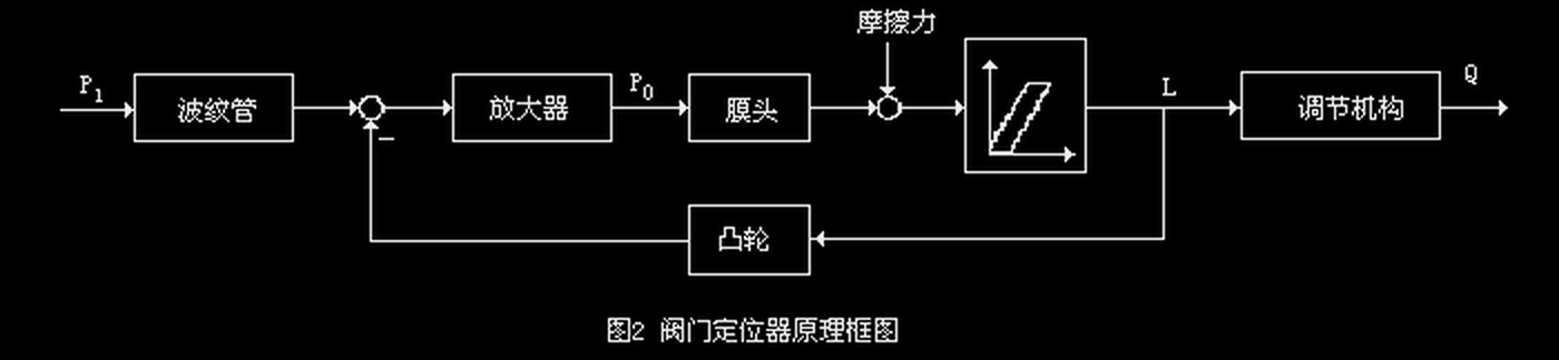
Figure 1. Positioner block diagram (original figure, dark scan re-processed)
4. The control-theory essence: a cascade inner loop
With a positioner fitted, the system becomes a cascade loop with stem position as the secondary variable. Three benefits follow:
- The equivalent time constant of the inner loop is greatly reduced (bellows air capacity is far smaller than the diaphragm case), improving valve dynamics;
- Strong rejection of disturbances entering the inner loop — friction, unbalanced force, hysteresis variations — which is exactly why positioners are fitted in high-friction, high-differential-pressure and slurry services;
- The cam in the feedback path reshapes inner-loop gain to compensate process nonlinearity, and changes the input span corresponding to full travel (split ranging).
5. ⚠️ Why can a positioner cause oscillation?
The most common field puzzle; the original papers give two mechanisms:
- Cascade resonance: once the inner loop is tuned as a follow-up system to a damped-oscillation state, the equivalent inner loop approximates a second-order oscillating element — near 1:1 at low frequencies, but at higher working frequencies it resonates with 180° phase shift, becoming positive feedback. When the controlled object has a small time constant (typically flow and fast pressure loops), mismatched time constants cause output oscillation;
- The cam introduces nonlinearity: reshaping the flow characteristic with a cam inserts a nonlinear element into the inner loop — an unsuitable cam profile or an unstable (high-gain) amplifier changes the total open-loop gain and violates the stability criterion. The typical symptom is oscillation at small flow; experience shows replacing the cam or amplifier stops it — precisely because the inner-loop total gain changed.
6. Three improvements of the smart electropneumatic positioner
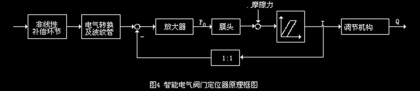
Figure 2. Smart positioner block diagram (original figure, dark scan re-processed)
- Wider nonlinear compensation: the compensation element sits in the forward path with manually settable range — even pH processes and distorted characteristics from pressure-drop ratios below 1 can be compensated, which ordinary positioners cannot do;
- Cascade resonance eliminated: adjust the inner-loop forward-path amplifier or the main-loop compensation gain to stagger the time constants of the main and secondary objects;
- Linear inner-loop feedback: nonlinear compensation moves to the forward path, the feedback path becomes linear (no cam), letting the inner loop concentrate on stem dead-band and friction disturbances.
7. Smart positioner features (A-G)
- A Better valve and system performance: high control accuracy, settable and custom valve characteristic curves;
- B Smart communication: HART most commonly — all plant-wide positioner parameters can be stored on a computer and re-downloaded in seconds during maintenance or replacement;
- C Binary input for interlocked open/close;
- D Software split-ranging: start/end points set by software or hand, quickly;
- E Very simple initialization: for the Siemens PS2, four button presses and a few parameters complete auto-initialization;
- F Rich diagnostics: valve leakage, packing, wear diagnostics are standard among major vendors;
- G Air and cost savings: about 0.3Nm³/h instrument air saved in normal operation, stabilizing the plant air network.
8. Five selection points
- Given site conditions are met, intelligence (communication, online/offline diagnostics) is the key criterion;
- Easy field operation: overly complex setup undermines real-world effectiveness — prefer simple products;
- Good value for money, energy and cost savings;
- Local display required: some products lack an LCD, forcing handheld-communicator tuning; for LCDs check legibility at very low ambient temperatures;
- Long-distance installation: with integrated control rooms common in large petrochemical plants, cable voltage drop from control room to positioner must be calculated, or the positioner will not work properly.
9. Four common faults and fixes
- Signal changes but valve does not move (valve body excluded): check that the position transmitter moves freely and the electrical signal is continuous;
- Position uncontrollable (no motion on small signal, full open/close on large signal, re-calibration futile): real case — the ND800's feedback lever connects to the signal-conversion section non-contactingly and can rotate 360°, having been installed 180° out of phase with the stem; refitting and recalibrating fixed it;
- Small-opening oscillation: conventional fixes are avoiding small openings or changing flow-to-close to flow-to-open (cumbersome); smart positioners improve it markedly with a simple parameter change;
- Handheld communicator will not connect: check field voltage >12V, output impedance <250Ω, cable capacitance not too high, input signal not below 4mA.
10. Conclusion
Traditional electropneumatic positioners have also improved in accuracy, sensitivity and stability, but domestic (Chinese) units still lag foreign smart products. Compared with traditional I/P positioners, smart valve positioners offer broader application prospects in control accuracy, response speed, functionality and valve automation — they are regarded as the future direction of the positioner.
Summary
- Seven cases: high friction, characteristic modification, wide-band small-signal, slow processes, high force, split-ranging/reversal, springless actuators — any one justifies a positioner;
- Two roots of oscillation: cascade resonance (flow/fast-pressure loops at risk) plus cam nonlinearity breaking total loop gain — the smart positioner's "compensation in the forward path, linear feedback" is the targeted cure;
- Selection in three: easy operation, local LCD (mind low temperatures), and voltage-drop calculation for long cable runs.
Need smart valve positioners and matched actuators sized and supplied? Submit an RFQ.
Related reading




