This design paper lays out a “DSP + variable frequency” route for the intelligent electric actuator: a TI TMS320F2812 control core, a three-phase asynchronous motor driven by an SVM-DTC (space-vector modulation – direct torque control) inverter, an IPM intelligent power module, eCAN (CAN2.0B) communication, and MMB (MicroMessage Bus) real-time multi-task software with field configuration. Three points carry real engineering flavour: (1) intelligent calibration needs only one key-press at the valve’s true full-open and one at full-close; (2) SVM-DTC makes the actuator “faster the larger the error, slower near the balance point”, sharpening fine-trim and positioning accuracy; (3) power-fail protection writes parameters to EEPROM periodically, shrinking the data-inconsistency window to a minimum. This is an academic design paper published in 2011 (concept and algorithm level, no measured product data), republished here as one approach to intelligent actuator control architecture.
The system comprises a drive controller, a three-phase asynchronous motor and the mechanical actuator: the controller uses the TMS320F2812 as microcontroller; the motor is a three-phase asynchronous machine driven by an SVM-DTC inverter for precise running and appropriate torque output; the power inverter uses an IPM. Overall structure in Fig. 1.
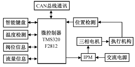
Fig. 1 System structure of the electric actuator (source: ocpv.net paper library, 2011-04)
| Module | Design as published |
|---|---|
| Controller core | TI TMS320F2812 — 32-bit fixed-point DSP with RISC + microcontroller architecture, on-chip eCAN |
| Motor & drive | Three-phase asynchronous motor + SVM-DTC (space-vector modulation – direct torque control) inverter |
| Power stage | Intelligent power module (IPM): switches and gate drivers integrated, with built-in over/under-voltage, overcurrent and overtemperature monitoring reported to the DSP |
| Communication | eCAN controller, fully CAN2.0B-compliant, robust serial communication in noisy environments |
| Software stack | MMB (MicroMessage Bus) distributed fieldbus system + real-time multi-task OS + component library + online configuration (MMBIDE, downloaded via OPC server) |
| HMI & sensing | LCD live display of opening/status/faults; infrared remote; configuration control; valve-position and machinery-data acquisition |
Rationale: a 32-bit fixed-point DSP with RISC and micro-controller architecture — high performance, low power — covering field data acquisition, analysis and control display; the software stack integrates a real-time multi-task OS, monitoring software, task-level configuration software and a real-time database with online configuration support, suiting industrial field control and bus systems. For communication the on-chip eCAN (derived from TI’s TMS470 HECC high-end CAN controller) is fully CAN2.0B-compliant and works in noisy environments, giving reliable real-time links to the host and other field devices.
| Protection / reliability | Mechanism |
|---|---|
| Over-voltage, over-current, over-torque | DSP monitors motor current/voltage continuously and computes torque; on violation it cuts motor power and raises an alarm |
| Motor overheat | Winding temperature sensor monitors continuously for alarm and thermal protection |
| Jammed-valve burnout prevention | If no motion occurs within a set time, the controller cuts power and alarms |
| Emergency position (ESD response) | On loss of control signal the actuator runs at a preset emergency speed to a user-chosen position: full open, full close or hold |
| Power-fail protection | Running parameters are periodically written to EEPROM so the data-inconsistency window is minimal |
| Intelligent calibration | One key-press at the valve’s true full-open and one at full-close completes calibration |
MMB (MicroMessage Bus) is a distributed fieldbus control system built on CAN: software-component technology applied to real-time embedded systems so users tailor the system by picking components; the MMBIDE environment handles configuration editing, compiling, downloading and debugging — components are compiled by the INVA virtual machine into machine code and downloaded to the instrument via an OPC server. Programs follow a modular split into communication, control and management: communication uses event-state polling plus CAN interrupts — normal data is packed and returned on host request, fault data is pushed immediately without waiting; management covers LCD display, mode management, alarm indication, key scanning, power-fail protection, interrupt service and self-diagnostics (program configuration in Fig. 2).
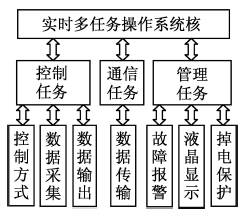
Fig. 2 Program configuration diagram (source: ocpv.net paper library, 2011-04)
The drive task runs on the laboratory’s own MMB fieldbus control system, configuring SVM-DTC for precise motor control and soft start/stop — reducing mechanical shock to the valve during starts (drive-task flow in Fig. 3). The control task measures motor torque, flux and speed, passes them through torque/flux comparators and uses bang-bang control to output switching signals for the inverter (control-task flow in Fig. 4). During modulation the servo speed adapts to the error: with a large gap between command and position feedback the motor runs faster than a conventional actuator; as the gap narrows the speed falls, and near the balance point the actuator creeps — greatly improving fine-trim and positioning accuracy.
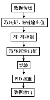
Fig. 3 Drive-task configuration flowchart (source: ocpv.net paper library, 2011-04)
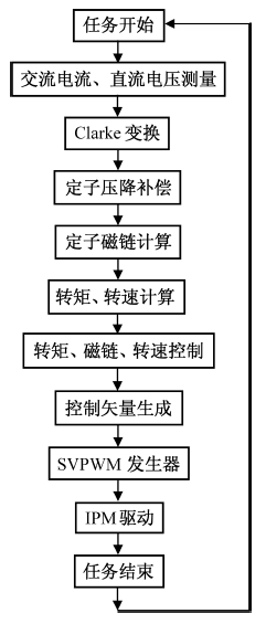
Fig. 4 Control-task configuration flowchart (source: ocpv.net paper library, 2011-04)
The CAN-bus intelligent electric actuator with a DSP core: simplified hardware, faster computation; highly intelligent, precise control; fieldbus communication enabling remote maintenance and management; more complete self- and system-protection; intelligent self-diagnosis for fast fault identification — with broad application prospects.
References: Wang Xiaoming, Motor DSP Control (Beihang University Press, 2004); Yuan Aijin, MMB Software Architecture (Dalian Sanhe Instruments, 2004).
Source: adapted/translated from the ocpv.net paper library, “浅议基于DSP的智能型电动执行器软硬件设计” (On the hardware/software design of a DSP-based intelligent electric actuator, published 2011-04; figures 1–4 from the original). An academic design paper — data and conclusions are the author’s proposal without measured data; actual products per the manufacturers’ documentation.
Need selection, commissioning or technical exchange for intelligent electric actuators? Submit an RFQ.






