The positioner makes dampers and louvres move as the operator intends, bringing the controlled object within the required range and keeping equipment safe.
At Heze power plant the F40- and F20-controlled dampers are vital to the air and flue-gas systems: FD-fan inlet cold/hot air louvres, six secondary-air louvres, furnace-bottom injection air, mill hot/cold air and mill bypass dampers. Their condition bears on major auxiliary protection and trips, unit derating, unstable combustion, furnace outage — even equipment damage. MB (the licenser) acknowledged that F40/F20 positioner quality is unreliable. Liaocheng plant's F40/F20 experience matched ours — very high failure rates threatening safe, stable operation — and Liaocheng replaced all F40/F20 positioners with ABB units, with clearly better results: steadier damper control and safer unit operation. To keep our units safe, stable and efficient, we converted the F40/F20 positioners to the reliable dual-output ABB positioner, long used on our other equipment — stable, low-failure, sensitive.
Currently the F40 and F20 I/P converters on boiler #4 often clog, leak, give unreliable feedback and poor linearity: dampers refuse to follow the operator, either sticking or slamming full open/close, pushing the controlled condition out of range and directly threatening the unit. With MB acknowledging the quality problem, the F40 positioners are being converted to the reliable dual-supply ABB positioner.
The conversion needs only a machined adapter between the ABB positioner and the existing cylinder; mount the ABB positioner on the cylinder via the adapter, reconnect air piping firmly, and re-position and commission with the mechanical crew.
The F40 organically combines microprocessor technology with the pneumatic control interface. The basic model is a 2-wire instrument: one standard 20 mA industrial signal serves both as control signal and as supply for the electronics, connected via plug connectors; the microprocessor makes setting very simple and quick. An automatic initialisation routine sets the basic functions — zero, span, speed, sensitivity — all at the push of a button (Fig. 1).
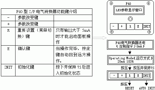
Fig. 1 F40 operating panel and menu navigation
For actuators of 60°, 90° or 180° travel the positioner automatically sets that range. Automatic performance monitoring ensures best performance even under large process changes. All common functions work for single- or double-acting actuators: split-range, reverse action etc. Two basic types exist — quarter-turn and linear — differing mainly in mounting and mechanical travel; both suit double-acting and spring-return actuators. The standard feedback system keeps input and output displacement linear, with optional settings for fast opening and equal percentage; the "user-defined curve" option yields 1,000 variants on the base characteristic. The built-in 5-key keypad and LCD make resetting easy, and base functions plus user settings live in EPROM — retained even after signal failure.
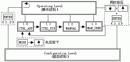
Fig. 2 F40 double-output actuator
The positioner places the pneumatic actuator anywhere between full open and full close, displacement proportional to the 4–20 mA input for precise control. Position is monitored by a feedback potentiometer; the analogue signals are digitised for the microprocessor. In normal running a comparator logic continuously compares command and feedback: equal — no output, the actuator holds at its "setpoint"; differing — the positioner commands one pneumatic valve or the other to move toward the new setpoint, the command ending when it arrives. Changed signals issue new commands until the new setpoint is met. The pneumatic control valves carry electrical control elements forming a high-sensitivity electro-pneumatic interface that determines system accuracy. Approach speed depends on distance to setpoint: large changes move fast at first; near the setpoint the pneumatics switch to pulsing, slowing the actuator progressively to a stop — precise final position without overshoot.
To initialise, connect the mA signal and press INIT — everything else is automatic. The positioner runs a series of cycles, electrically setting the basic functions (zero, span, speed, sensitivity).
Mount the positioner on the actuator, connect the air and the mA signal set to 20 mA; press "+" or "-" to display the input. If the LCD shows 20 mA, go to step 4; if not, check the signal and wiring. Press INIT: the positioner runs its initialisation, first establishing defaults, then diagnostic settings, the LCD showing progress.
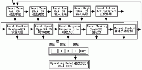
Fig. 3 Initialisation self-tuning
Stroke the actuator several times — mechanically setting the potentiometer indication; stroke once more — establishing zero and span; stroke once, pausing at several positions — measuring travel time and setting the speed threshold; move to mid-travel and make several short strokes — optimising the dead band for the current application.
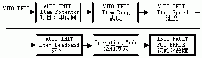
Fig. 4 F40 parameters
On successful completion the positioner switches to "operating mode", ready. The mA signal may now be disconnected; on reconnection no re-initialisation is needed.
The F40 performs poorly and ages fast: internal rubber seals age; control output linearity is poor; the air chambers leak and cross-leak; the control output orifice is small and clogs easily — unstable control air, sluggish actuators, dampers losing control, conditions out of range, unit safety affected.
Remove the F40; machine the adapter between ABB positioner and existing cylinder; assemble positioner to adapter and mount on the cylinder; redo piping and wiring; power up; mechanically set damper positions; individual commissioning, then system joint commissioning to the working standard.
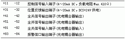
Table 2 TZID-C wiring terminals
The heart of the TZID-C is its microprocessor CPU, where all program processing occurs. Input and position feedback pass through a 12-bit, 4,000-step A/D converter sampling every 20 ms, ensuring precision and speed. The CPU is powered directly from the input signal. The operating program includes auto-tuning for automatic parameter adjustment and an adaptive control program for optimised precise positioning: the electro-pneumatic converter with a 3/3-way amplifier drives the pneumatic actuator — the CPU's positioning signal converts proportionally to pneumatic, proportionally regulating the 3/3 pneumatic switch, both supply to the actuator and exhaust being proportional; on reaching the setpoint the 3/3 switch locks in neutral. The TZID-C panel carries two LCD rows and 4 keys (Fig. 5).
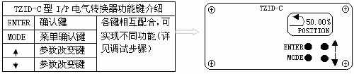
Fig. 5 TZID-C function keys
The optimised keypad suits local configuration, calibration and monitoring. Configuration, operation and monitoring also connect to a PC over HART via the built-in port, or through an FSK modem tapped anywhere on the 4–20 mA line. Modular design extends the base unit at will: insert the relevant module for analogue or digital feedback, with optional limit switches (microswitches) and mechanical indicator.
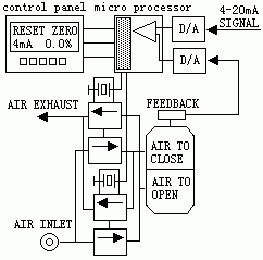
Fig. 6 TZID-C functional principle
Open the air and check reducer pressure against the actuator nameplate (positioner maximum supply is 7 bar, but actual pressure must respect the actuator's maximum); connect the 4–20 mA input (the positioner is loop-powered from the DCS two-wire loop — never apply 24 V DC directly, or the circuit may be damaged).
Wire per the terminal diagram and design (usually only +11, -12, +31, -32).
Check the feedback lever's mounting angle (if positioner and actuator shipped as one unit, the supplier has done this — just confirm; not mandatory): hold MODE while tapping ↑ or ↓ until operating mode 1.3 shows; release MODE; with ↑/↓ run the actuator to both end positions and note the angles. They should fall within the recommended ranges (minimum angular travel 20°, symmetry not critical): -28° to +28° for linear, -57° to +57° for quarter-turn, total travel not less than 25°.
Switch to the parameter menu: 11 groups, P1._ to P11._ (P for PARAMETER), each with items — P1._ has P1.0 to P1.4 (5), P2._ has P2.0 to P2.7 (8).
Some items branch: P1.0 offers LINEAR for linear actuators and ROTARY for quarter-turn; P1.4 EXIT offers NV-SAVE (non-volatile save) or CANCEL (exit without saving). Some items are numeric: for split-ranging with a 4–12 mA command set P2.0 to 4 mA and P2.1 to 12 mA; for 12–20 mA set P2.0 to 12 mA and P2.1 to 20 mA.
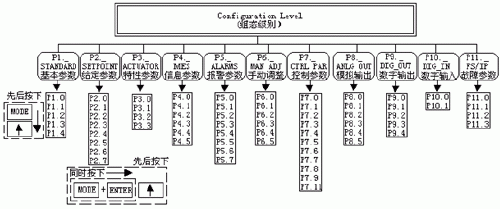
Fig. 7 Configuration menu
Hold ↑ and ↓ together and press ENTER; after 3 s (counter from 3 to 0) release them — the program enters menu P1.0. Then select linear or quarter-turn mounting.
Quarter-turn: no feedback lever — the feedback shaft is coaxial with the actuator output, usually 90°. Linear: the positioner is driven via a feedback lever whose angular travel is under 60°, for linear-stroke pneumatic actuators.
Note: before auto-tuning, confirm the actual mounting matches the menu selection — the terminal definitions and linearisation database differ, and mismatches cause large nonlinear errors.
Start auto-tuning (recommended after installing the actuator/valve in the system): hold MODE and tap ↑ until "P1.1" shows; release MODE; hold ENTER 3 s until the countdown reaches 0 and release — auto-tuning runs (the display shows the running step). On success "COMPLETE" appears; on fault the program halts with a fault code for diagnosis. Manual interruption is also possible.
If needed, enter P1.2 to adjust the control deviation band (dead band) and P1.3 to test the setting effect.
Store results: hold MODE, tap ↑ until "P1.4" shows, release; choose NV-SAVE with ↑/↓ (CANCEL discards changes); hold ENTER 3 s until the countdown finishes — settings and auto-tuning measurements store in EEPROM and the positioner returns to its previous operating mode.
Normally choose 1.0 for remote automatic control. Only when actual travel is very small and the actuator fast, causing oscillation, choose 1.1 — at lower control accuracy.
Modes 1.2 and 1.3 both open/close the actuator from the keypad: 1.2 is dedicated manual operation; 1.3 checks whether the feedback lever's actual range exceeds the sensor's detection range, to correct the lever linkage for best control.
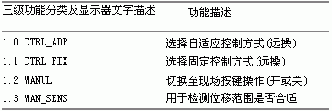
Table 3 Three-level function classes and display texts
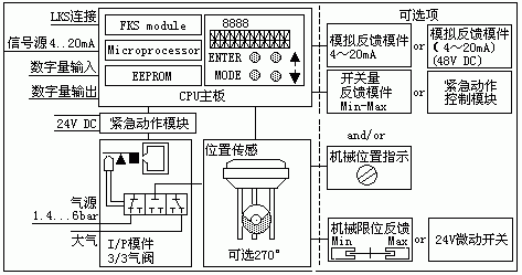
Fig. 8 Parameter configuration
After conversion, positioner failure rates fell markedly — dampers no longer lose control repeatedly and control is steadier; control-air output is linear, eliminating converter failure or spurious action, securing combustion and unit safety; spare-part replacements and maintenance costs dropped.






