Abstract: This article introduces the lightning-protection ports of instrumentation, explains why port protection is necessary, and sets out the basic principles of protecting instrument lightning ports.
Keywords: instruments; lightning-protection ports; port protection
Electrostatic discharge (ESD) and electrical fast transients (EFT) harm instrument systems to varying degrees. ESD radiates strongly across 5–200 MHz, with peak energy often self-oscillating between 35 and 45 MHz — exactly where many signal cables resonate, so cables pick up large amounts of ESD radiation. EFT also radiates strongly, coupling into cables and chassis wiring. With a cable exposed to 4–8 kV ESD, induced voltage at the cable-end load can reach 600 V — far above the 0.4 V threshold of typical digital instrumentation — with typical induced pulses lasting about 400 ns.
Instruments often meet unexpected voltage transients and surges that destroy electronics — semiconductor devices (diodes, transistors, thyristors, ICs) burn out or break down. Statistics attribute 75% of instrument faults to transients and surges. They are everywhere: the mains, lightning, blasting — even a person walking on carpet generates tens of thousands of volts of static. Invisible killers all; protection is required for both reliability and personal safety.
Engineering practice sorts instrument lightning strikes into direct, induced and conducted. Whatever the form, surges enter through four ports:
Any instrument or system — sensor, transmission line, repeater, field instrument, DCS — can be seen as one enclosure, exposed to direct strikes. Standards say a 4 kV ESD on the enclosure disturbs normal operation: an outdoor sensor terminal box may take contact discharge; an indoor DCS cabinet may see air discharge from current down a building column.
Signal transfer needs connections to the outside world — main distribution frames, network terminals, microwave feeder ports — all expose interfaces to surge冲击. Surges entering from outside buildings travel long cables, so the 10/700 μs waveform applies: 0.5 kV line-to-line, 1 kV line-to-earth. Ports passing signals between instruments inside a building see surges like mains ones: 1.2/50 (8/20) μs, 0.5 kV line-to-line, 1 kV line-to-earth. Otherwise equipment behind the port may be damaged.
The most widespread and most easily coupled port — anywhere from distribution boxes to sockets. Standards limit surges at 1.2/50 (8/20) μs to 0.5 kV line-to-line and 1 kV line-to-earth, for 220 V AC working voltage; at lower working voltages that limit does not apply. Modest surges on power lines may not destroy equipment at once but do shorten life.
Though standards name no specific index for it, the earth port matters greatly: during strikes it suffers earth-potential rise and back-flashover, and poor or wrong earthing — excessive resistance failing the reference potential — damages equipment. The earth port imposes requirements on resistance and electrodes (length, diameter, material), earthing method and grid layout, and relates directly to equipment electrical characteristics, frequency band and environment; it can also back-strike the DC supply port and damage DC-powered devices.
In sum, lightning protection for IT equipment starts from these four key ports (Fig. 1).
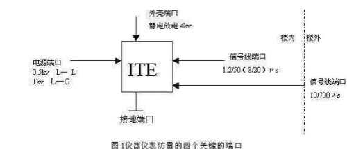
Fig. 1 The four lightning-protection ports
Enclosure protection covers not just buildings but equipment and system housings — cabinets, computer rooms. IEC 1312-1 (Protection against lightning electromagnetic impulse, Part 1: general principles) covers the design, installation, inspection and maintenance of effective lightning protection for instrument systems inside or on top of buildings. Three main methods: earthing, shielding and equipotential bonding.
2.1.1 Earthing. IEC 1024-1 describes building lightning earthing via the underground grid. Instrument systems must also connect power and communication lines running between adjacent buildings to the building earth (without forming loops), using parallel paths to reduce cable currents. System earthing must mind safety and interference from other systems: in operation an instrument system earth must not connect directly to the lightning earth, or stray currents enter and disturb signals. Correctly, the two earth grids join underground through a spark gap (low-voltage arrester) that closes automatically during a strike.
2.1.2 Shielding. Theoretically very effective for enclosures, but economics dictate the shielding method from component immunity and required shielding effectiveness. Cable shielding is widespread; equipment/system shielding depends on circumstances. IEC cites connecting building rebar to metal frames. IEC 1312-2 notes: the main electromagnetic disturbance inside buildings is the transient magnetic field from the impulse currents of a few strokes of one flash; large-space shielding of the building or room reduces the transient field to a sufficiently low value.
2.1.3 Equipotential bonding. Bonding reduces potential differences between instruments and between instruments and metal parts. At lightning-protection zone boundaries consider the instrument system: where EMP effects matter least, bonding bars should be metal plates, multiply connected to rebar or other shielded structures. Exposed conductive parts should form an equipotential network; in principle such a network need not be directly earthed, though in practice all are connected to earth.
Mature protectors abound: interface protectors for instrument signal networks, antenna-feeder protectors, security units for terminals. Beyond inherent performance, watch transmission rate, insertion-loss limits, VSWR, working voltage and current; with multi-stage protection in one system, coordination matters. Notably, commercial pressures lead to too many protectors per network — lowering speed, raising loss, distorting transmission, losing data. In my view, fit suitable protectors at the interfaces where network signals enter and leave, and that suffices.
Transient currents entering signal ports most easily destroy switching/conversion units and process computers — motherboards, parallel ports, interface cards. Surges reach signal networks by many routes; IEEE 802.3 lists four threats: (1) direct contact between LAN elements and power circuits or affected circuits; (2) static on LAN cables and elements; (3) high-energy transients coupling into the LAN (from cables near network cables); (4) small earth-potential differences between interconnected network elements (e.g. safety earths of two different buildings).
Take data lines: in RS-232 serial/parallel standards the earth draining surges and fault currents shares a path with the data return, so even tens of volts of transient through these ports can destroy computers and printers; signal lines conduct mains transients from outdoors directly, and interfaces conduct lightning and static surges.
Choose data-line protectors carefully: some "shunt" via silicon avalanche diodes (SAD) between the protected line and the protector case — good clamping but limited surge capacity; MOVs are also unsuitable on data lines. Advanced process-control signal interfaces (RS-232 etc., coax network adapters) now use transient-overvoltage semiconductor discharge tubes, where residual impulse voltage matters; multi-stage design is better still.
Antenna-feeder protectors work on waveguide-shunt principles: transmit power 400 W, rated discharge current (8/20 μs) 5 kA, frequency below 2.5 GHz, insertion loss below 0.8 dB, response under 100 ns.
In principle use multi-stage SPDs, but information systems' sensitivity demands low-residual-voltage devices, below the protected equipment's withstand — and electromagnetic interference on instruments must be considered, so filtered shunt designs are ideal. Two points matter for instrument power protection: the first stages use high-current-capacity protectors, the instrument end uses low-residual-voltage ones, and the last stage ideally includes filtering. Installing SPDs on instrument power ports, note: (1) multi-stage SPDs need energy, time and distance coordination — bad coordination backfires; (2) connecting leads should be as thick and short as possible; (3) in full protection, bundle all connecting leads together.






