Abstract: Drawing on instrument principles and field practice, this article analyses why interference disturbs instrument operation and proposes concrete remedies and preventions. Keywords: series-mode interference; common-mode interference; shielding; earthing; distributed capacitance
Field conditions for instruments are often complex, and measured quantities are usually converted into weak low-level voltage signals transmitted long distances to secondary instruments or computers. Besides the useful signal, unrelated voltages or currents often appear — "interference" (noise).
Interference has many sources. Commonly we mean electrical interference, but broadly thermal noise, temperature effects, chemical effects and vibration all disturb measurement. Unless excluded, the instrument cannot work properly.
By the mode of action at the instrument input, interference divides into series-mode (superimposed on the measured signal) and common-mode (between either input and earth).
Interference comes from sources inside and outside the instrument. Outside, high-power electrical and power equipment can be sources; inside, supply transformers, relays, switches and power lines can too. The main entry routes:
1) Electromagnetic induction — magnetic coupling. Signal cables and internal wiring form loops in which the strong alternating fields around large transformers, motors and HV networks induce EMFs: e = B·A·cosθ (e — induced EMF; B — flux density; A — loop area; θ — angle between field and loop normal). The induced EMF is in series with the useful signal, most prominent when source and instrument are far apart (Fig. 1.1, experimental data).
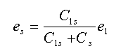
Fig. 1.1 Magnetically coupled interference (experimental data)
To reduce the induced EMF, minimise B, A or cosθ: keep wiring away from heavy electrical plant, route carefully, shrink loop area. Merely twisting the two signal wires with a short pitch cuts magnetic induction to 1/10–1/100.
2) Electrostatic induction — capacitive coupling. When one of two facing objects changes potential, capacitance couples the change to the other — interference from the interplay of two fields (Fig. 1.2). Wire 1's potential induces an earth-referenced voltage on wire 2. When signal lines run parallel to power lines, the unequal distances create unequal distributed capacitances, generating potential differences of tens of millivolts or more between the signal wires. Twisting greatly reduces this difference; electrostatic shielding reduces induced EMF to 1/100–1/1000.
Interference from electromagnetic and electrostatic induction is mostly 50 Hz mains hum, but high-frequency generators, commutator motors etc. produce high-frequency interference too, and lightning discharges between clouds or to earth induce abnormal voltages on wiring.
3) Thermal and chemical EMFs. Thermoelectric EMFs between dissimilar metals and chemical EMFs from corrosion act in circuits as interference, mostly DC. Terminal strips and dry-reed relays are prone to thermal EMFs.
4) Vibration. A wire moving in a magnetic field generates EMF — fix signal wiring in vibrating environments.
These four appear in series with the signal — series-mode interference.
5) Interference from differing earth potentials. Potential differences exist between points of the earth, larger near high-power equipment with poor insulation. Instruments often have — deliberately or not — two or more earth points in the input loop, importing earth-potential differences of 1–10 V or more, appearing on both signal wires simultaneously (Fig. 1.3). Capacitive coupling induces a common earth-referenced voltage on both inputs — common-mode interference. Not superimposed on the signal, it does not act on the instrument directly, but it drives leakage currents to earth through the measuring system, and through resistive coupling those currents act on the instrument.
6) Pulse interference. Pulse voltages disturb digital as well as analogue circuits; sources include inductive loads — switches, motors, relays — and discharge machinery.
Knowing the sources, we can counter each case. Since all interference reaches the instrument through coupling channels, cutting those channels suppresses it: wire twisting, shielding, earthing, balancing, filtering, isolation — usually several at once.
Many measures exist; suppression demands a full analysis, acting on three fronts: eliminate or suppress noise sources, break interference paths, reduce the receiving circuit's sensitivity.
Removing noise sources is the active measure — poor contacts and cold joints can be fixed, and in principle sources should be eliminated. But many cannot be: a pump house instrument cannot escape the motor's electromagnetic interference while the pump runs. Then protective suppression is required.
Series-mode interference sits where the signal sits — once present it is hard to remove, so prevent it:
* Twist the signal wires. Twisting shrinks the loop area, keeps both wires equidistant from the source and equalises distributed capacitance — greatly reducing magnetically and electrostatically coupled series-mode interference.
* Shielding. Wrap signal wires in metal — usually a metallic (or ferromagnetic) braid under insulation — to break "field" coupling. The screen must be earthed to work. Fig. 2.1 compares earthed and unearthed screens: wire 1 is the interferer, wire 2 the signal wire with effectively infinite resistance to earth, wrapped in a screen. Unearthed, the distributed capacitance between source and screen induces a voltage on the screen; with capacitance C2s between wire 2 and screen carrying no current, wire 2's induced voltage e equals e_s. Earthed, e_s = 0 and wire 2's induced voltage falls to near zero — so the screen must be earthed or it achieves nothing. Note non-ferromagnetic screens have no effect at mains-frequency magnetic interference: run signal wires through steel conduit for magnetic shielding.
Fig. 2.1 Screen earthed versus unearthed
* Filtering. For very slowly varying DC signals, input filters minimise interference mixed into the signal — though in engineering practice this is rarely applied separately, being handled inside the instrument's circuit design.
These are passive measures after an interference field forms. Practically, avoid forming the field: keep signal wiring away from power lines; route sensibly to limit stray fields; magnetically shield transformers and the like — active isolation.
Instrument signals are mostly low-level, so common-mode interference distorts them and corrupts measurement. Usual measures:
* Earthing. Instrument and source cases are earthed for safety at zero potential, and source circuits and instrument systems need stable earths. But wrong earthing forms earth loops importing interference — exactly Fig. 1.3: two earth points with a potential difference create common-mode interference. So instrument loops usually single-point-earth at the system side. In reality the source side cannot float perfectly, so earth-potential interference can never be entirely eliminated. To strengthen immunity, low-level instruments float the secondary instrument — insulating it from earth to cut the common-mode leakage path. In practice combining shielding with earthing solves most problems. If the screen is earthed at both source and instrument ends, earth potential differences drive currents through the screen; since earth resistance is far smaller than screen resistance a potential gradient forms on the screen and couples via distributed capacitance into the signal circuit — so the screen must be earthed at one point only, and on the same side as the system earth.
In fact the secondary instrument's case is earthed for safety, and distributed capacitance and leakage impedance inevitably exist between input and case, so floating never cuts leakage completely. When necessary use double-screen floating guard: an inner shield inside the case, connected neither to the input nor the case, its lead joined to the signal-cable screen, the cable screen earthed at one point at the source — holding the input guard and cable screen at source potential, greatly improving immunity (Fig. 2.2). Some leakage still remains, but suppression aims only to reduce interference below what matters against the true signal.

Fig. 2.2 Double-screen floating guard
Isolation is another common measure, suppressing interference by preventing loop formation. Effects are additive; usually one or more methods combine to raise measurement immunity. Theory and practice keep adding measures — this article only sketches those common in engineering, hoping it helps.






