With strong functionality, simple programming and easy maintenance — above all high reliability and tolerance of harsh industrial environments — PLCs are widely used in the water industry. But poor site conditions, high humidity and industrial electromagnetic/radiation interference affect normal operation, so anti-interference design must be taken seriously. In waterworks the interference sources fall into three classes: via the power system, via the earthing system and via I/O circuits. If not solved, the system cannot run reliably and normal water supply suffers. This article discusses the three anti-interference techniques.
Both hardware and software measures apply, hardware being the most basic and important: suppress and remove interference sources, cut the coupling channels into the system, and lower the system's sensitivity to interference.
Mains disturbances and frequency fluctuations directly affect PLC reliability and stability; suppressing them is the main lever.
(1) Filtering, isolation, shielding and switching regulated supplies. Filters stop interference conducted along power lines. With an isolation transformer: earth the screens well; use twisted pairs on the secondary; screen primary and secondary separately — primary screen to mains neutral, secondary screen and inter-winding screen to the DC end. To counter voltage dips from large motor starts (e.g. supply pumps) and hold the supply steady, use a switching regulated supply.
(2) Separated supplies. Power the controller and the I/O system from separate isolation transformers, both separate from the mains, so an I/O power loss does not affect the controller (Fig. 1).
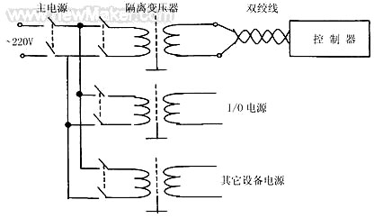
Fig. 1 Separated supply system
PLC systems distinguish logic earth from power earth, with common-earth, floating, and case-earthed/circuit-floating arrangements. Best practice is separate earthing for the controller and other equipment. Notes: use thick earth leads (≥2 mm²); keep the earth point within 50 m of the controller; keep earth leads away from power circuits — where unavoidable cross at right angles and minimise parallel runs. Good earthing suppresses internal noise coupling and blocks external interference.
For complete I/O isolation, optocouplers are now ubiquitous and one of the most effective defences. Their merits: sealed in one package, immune to ambient light; signal transfer by light severs earth continuity between circuits; the LED's dynamic resistance is tiny while interference source impedance is large, so little interference reaches the output; and the transfer ratio is far smaller than a transistor's gain — the LED only emits with sufficient current, so even high-amplitude interference without enough energy cannot light it, effectively suppressing the noise. Since the linear region of an optocoupler is limited, keep the signal within it; choose couplers strictly and apply nonlinearity correction, or errors will be large.
(1) Optocoupler input circuits (Fig. 2): (a) and (b) are common — (a) for high-level, (b) for low-level inputs. (c) is a differential connection with two constraint conditions, clearly superior against interference and suited to high-noise environments; with higher external equipment currents, transmission reaches 100–200 m. (d) adds a transistor driver stage because CMOS output current cannot directly drive the LED. Note LED and phototransistor should be fed from two separate supplies, with resistors chosen per voltage.
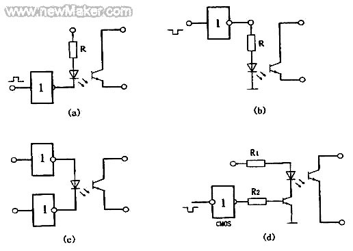
Fig. 2 Optocoupler input circuits
(2) Optocoupler output circuits (Fig. 3): (a) in-phase output; (b) inverted; (c) adds a transistor driver stage when driving heavier loads. For cleaner waveforms the output can pass through a Schmitt shaper.
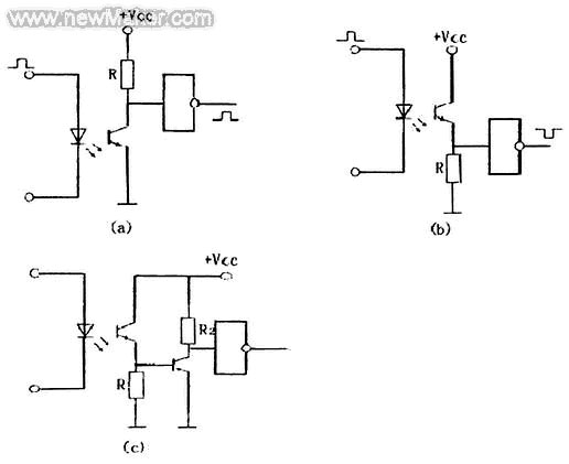
Fig. 3 Optocoupler output circuits
The above cover digital I/O. For analogue I/O, besides A/D, D/A conversion and optocoupling, software digital filtering — median, first-order recursive etc. — can be applied as needed against transient site interference.
Anti-interference design of PLC systems is a systems-engineering task involving specific I/O devices and the industrial environment; all factors must be weighed together.






