Keywords: valve electric actuator; intelligent controller; MC68HC908SR12
Water, steam and oil are bound up with industrial development; fluids need piping networks, and networks need valves. As industrial automation spreads, manual mechanical adjustment no longer suits many applications. Automating a piping network is unthinkable without the electric valve — the network's actuator. In some applications valve control goes beyond open/close to opening-degree and flow-relationship control, demanding more intelligence from the actuator controller. This paper presents a microprocessor-based valve control system making actuator control intelligent.
The controlled variable is valve opening. In practice valves are opened, closed, partly opened, or even dynamically stroked in a pattern. Traditional analogue control represents opening by time or current magnitude; since many factors affect those parameters the displayed opening rarely tracks the real position, with visible errors — and simple analogue control provides too little information for commissioning and maintenance. The intelligent system presented here controls the actuator digitally; its structure is shown in Fig. 1.
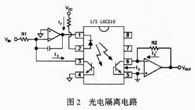
Fig. 1 Intelligent controller structure
A Motorola microcontroller plus peripheral chips form an intelligent position-control unit. It receives a standard DC signal (e.g. 4–20 mA), conditions and A/D-converts it to the microprocessor, which sends results to the display and produces control signals driving the AC motor. The system also communicates, accepting host commands for remote digital control, while the local HMI menu and buttons provide manual field control.
Main functions:
Guided by intelligence, reliability, interference immunity and low cost, the core is the 8-bit MC68HC908SR12 (SR12) with power electronics for the motor circuit. The SR12 is fast, capable and cheap: up to 8 MHz, 512 B RAM, 12 K FLASH, 14-channel 10-bit A/D, and SCI/I2C/SPI interfaces.
The internal A/D samples valve position and command signals; a filtered PWM output carries the position signal; the I2C bus stores settings in an AT24C08; the SCI talks to the host via MAX485 — fully exploiting on-chip resources and saving cost.
The internal A/D quantises the command and position-feedback analogue signals. A REF02 provides the A/D reference, temperature drift 3 ppm/℃.
The SR12 has three 8-bit high-speed PWM channels with independent counters, selectable clocks for various PWM frequencies and automatic phase control. One channel serves as analogue output, two as motor controls; I/O pin PTB6 drives a relay digital output.
Industrial use brings interference and dangerous high voltages from instruments, sensors and actuators. For safety, measurement correctness and reliability, optocouplers LOC210 isolate I/O (Fig. 2): the left side carries the CPU's digital earth, the right side the external system earth, with external and internal supplies fully separated.
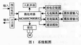
Fig. 2 Optical I/O isolation
For remote control and networking, RS-485 is supported via a MAX485 level converter, exchanging data with the host for mode setting and status monitoring.
The motor is driven by bidirectional thyristor BTA16 — fast switching, long life, no sparks or arcing — ensuring reliable high-temperature operation and protecting the motor. The power circuit couples to the CPU through MOC302X optodrivers (Fig. 3, ZL = motor load).
MOC3020 diode forward current is 15 mA, MOC3021/3023 8 mA and 3 mA, so the SR12 I/O pins can drive them directly by current sinking. RC snubber values depend on motor parameters. Note MOC302X withstands 400 V: for 380 V motors or large back-EMF, use the MOC308X series.
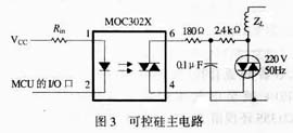
Fig. 3 Motor drive power circuit
The software comprises the main program plus HMI handling, auto-commissioning, fault handling, A/D and data processing, and manual-operation fault subroutines (Fig. 4). During execution fault states are judged; on detection the system alarms immediately, outputs a set of relay signals to the user and cuts motor power.
Four keys with multiple functions control the system: F (function — enters the setup menu; repeated presses exit), U/D (increase/decrease values or choose parameters; up/down commands in manual), S (shift — moves the input focus; with U/D any number can be entered easily).
PID control of the motor avoids overshoot and hunting; direct proportional or proportional-plus-step modes suit different motors. The valve end positions can be re-tuned at any time — after setting the limit switches, one auto-tuning (press F+S for 10 s) suffices, greatly easing commissioning. The RS-485 protocol lets users program valve control from a host, making networking and computer control convenient.
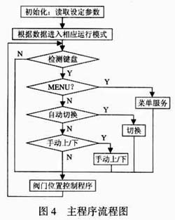
Fig. 4 Main program flow
Concentrating the main function blocks in one microcontroller cuts cost, raises reliability and shrinks volume — the controller installs inside the actuator without mechanical changes, easing both new production and retrofit of old units. The hardware design fully considers the industrial environment with thorough anti-interference and fault protection. The system is in production and runs well in various industrial settings.






