The SMC series valve electric actuator is the mainstay of the Limitorque valve actuator line, concentrating the essence of Limitorque technology; a number of actuator variants are derived from the SMC series.
Depending on the type of valve driven, Limitorque actuators come in two basic forms: the first controls multi-turn valves such as gate, globe and diaphragm valves; the second controls part-turn valves such as ball, butterfly and plug valves.
Part-turn actuators are further divided into combined (stacked) and integral constructions. The combined type is a one-stage multi-turn unit coupled to a second-stage reducer; the integral type houses the whole reduction system in one main housing. Practice shows the integral part-turn actuator is an economical product: smaller, but lacking many advantages of the combined type, so the combined type is preferred where control performance matters. Limitorque actuators are high-grade products, hence their part-turn range is mostly combined-type.
Combined construction also exists in multi-turn actuators — the most typical example being the SMC series combined with the BA series bevel gearbox, detailed below.
By output torque (frame size) the SMC series has four mechanical constructions: SMC-04 and SMC-03 (small torque) share one construction; SMC-00, SMC-0, SMC-1 and SMC-2 (medium) share another; SMC-3 and SMC-4 (large torque) a third; and SMC-5, close to SMC-3/4, is the largest-torque model made in China.
The figures below are axonometric or sectional drawings of the various frame sizes: Fig. 20 — SMC-04/03 parts section; Fig. 21 — SMC-00/0/1/2 axonometric; Fig. 22 — SMC-04/03 sectional construction; Fig. 23 — SMC-00/0/1/2 schematic; Fig. 24 — SMC-3/4 sectional construction (actually the SMB-3/4 section, which differs from SMC only in the travel-control part and is given for reference). SMC-5 is more complex than SMC-3/4 and, being rarely used, is not illustrated.
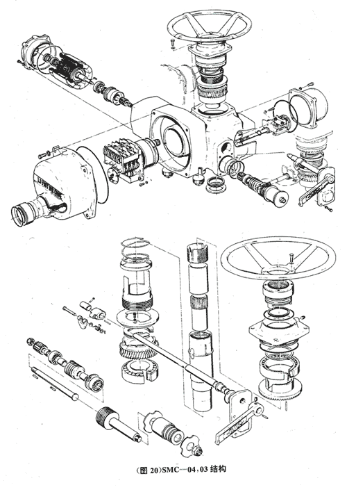
(Fig. 20) SMC-04/03 construction
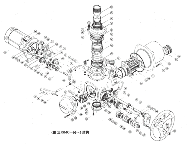
(Fig. 21) SMC-00~2 construction
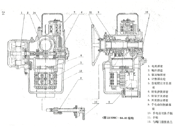
(Fig. 22) SMC-04/03 construction (section)
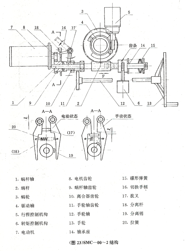
(Fig. 23) SMC-00~2 construction
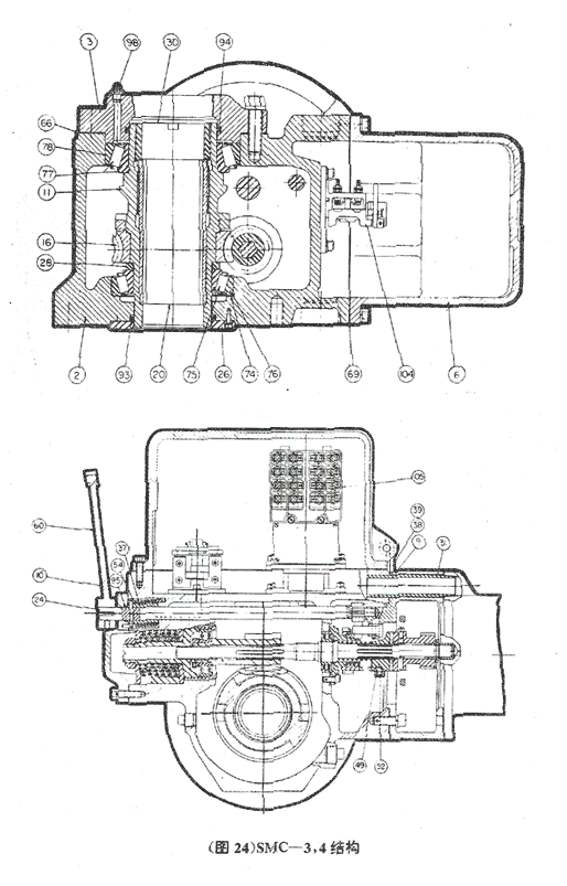
(Fig. 24) SMC-3/4 construction (section)
The small-torque SMC-04/03 use a conventional drive train: motor power passes through the motor gear and worm gear to the worm and wormwheel, then to the hollow drive shaft, which turns the stem nut to move the stem up and down (for rising-stem valves; for non-rising stems the hollow shaft rotates the stem).
Travel-control motion is taken from the large bevel gear on top of the hollow drive shaft — a speed-increasing drive beneficial to travel-setting accuracy. The motion enters the counter mechanism and, through intermittent gears, reaches the rotary contact switch that controls travel position (the SMC travel mechanism has many contacts for valve-position signalling).
Torque control consists of the torque-spring assembly and torque switch. The spring assembly sits at the end of the worm: when output torque reaches a set value the worm experiences axial force, compressing the disc springs and displacing the worm; this displacement, via a ring rack on the worm bearing housing, turns the torque-switch pinion and actuates the switch.
The indicator mechanism below the travel contacts provides local pointer indication and a continuous electrical position signal. It is a set of small-module gears whose ratio can be changed to suit any valve bore, so the pointer always reads full scale.
Travel and torque mechanisms sit on either side of the main housing. With a local pushbutton station the torque-switch enclosure is larger and carries the lamp box on top. Explosion-proof versions carry an Ex torque-switch assembly (basic or integral Ex); unlike the standard aluminium enclosure it is cast iron with an Ex terminal compartment. The travel side carries a travel-control cover whose length depends on the contact count — 4R-2C or 4R-4C.
Standard SMC-04/03 housings have two cable-entry holes. On the basic version the terminal board sits in front of the travel mechanism, with terminals also on the contact fingers — very convenient. With a pushbutton station the terminal board moves into the torque-switch box, which has two entries. On Ex versions the housing has no entry holes; cables enter through the Ex terminal box. Figs. 20 and 22 show the basic standard construction without torque-switch box or lamp box — note this when reading them.
SMC-04 and SMC-03 differ in rated torque (different frame sizes) but share flange dimensions (stem diameter differs). Their main constructional difference is motor mounting: SMC-04 has an internally mounted motor (stator and rotor inside the main housing), while SMC-03 has a separately housed motor (early SMC-03 units were also internal; the change came because larger motors are impractical to mount internally). Figs. 20 and 22 show the motor inside the housing — i.e. SMC-04 construction.
As medium-torque models, SMC-00~2 differ considerably from SMC-04/03 (compare Figs. 20/21 and 22/23). The different construction suits the higher torque: handwheel force, stem bore, manufacturability, volume, etc. Many parts are common with SMC-04/03 — most of the travel mechanism, most of the torque switch, the indicator — and some parts are interchangeable.
The main differences are:
Travel and torque mechanisms again sit on either side of the housing; standard, pushbutton-station and Ex variants change much as on SMC-04/03.
SMC-3/4 are the large-torque multi-turn models, essentially identical to the previous-generation SMB large sizes.
The drive arrangement resembles SMC-00~2, but the wormwheel and output shaft are so large that taking travel motion from the low-speed end is impractical — so SMC-3/4 take travel motion from the worm shaft. The main housing is also too large for side-by-side travel/torque arrangements, so both go into one square control box.
Because that box uses a flat square gasket, outdoor performance is slightly inferior to SMC-04/03 and SMC-00~2.
The control box has cable-entry holes (standard type); a pushbutton lamp box can be added on top of the main housing. The box interior is roomy enough for contactors etc. in integral versions.
SMC-3/4 Ex versions were redesigned for Chinese conditions and look quite different from the standard type; being rarely used they are not illustrated. Fig. 24 shows the standard SMC-3/4 section.
Chapter summary — The SMC multi-turn actuator consists of: a. dedicated valve motor; b. worm shaft and torque-spring assembly; c. hollow drive shaft assembly; d. travel-control assembly; e. indicator assembly; f. torque-control assembly; g. hand/electric changeover and manual assembly; h. others. This chapter lays the foundation for the following chapters, which describe each assembly in turn.
SMC actuators support many control schemes: standard basics as well as customer-specific wiring and special functions. This chapter presents several typical schematics.
Fig. 42 shows basic scheme (1). The travel mechanism uses only two normally-closed and two normally-open contact pairs — the usual 4R-2C count. NC contacts SL4 and SL8 control travel position; SL2 and SL6, actuated in step, indicate position. The scheme uses a large-contact NC torque switch whose contacts SL0 and SLC are in series with SL4/SL8 for torque control/protection. Torque indicator lamps H1/H2 are XD0 type 220 V. An ordinary potentiometer RP1 provides the opening feedback signal (stabilised supply as required). Space heaters RP1/RP2 sit in the terminal compartment; the unit has no local pushbuttons. The "customer wiring" part of Fig. 42 is in the control room; we supply a matching controller.
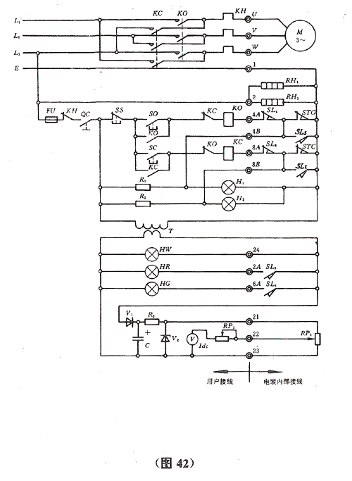
(Fig. 42) Basic scheme (1)
Fig. 43 differs from Fig. 42 by adding normally-open torque-switch contacts; torque lamps become XDX-6.3 V. A matching controller is available. In practice an extra torque lamp can indicate open and close torque trips separately.
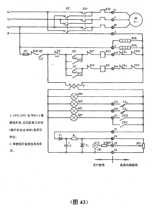
(Fig. 43) Basic scheme (2)
Fig. 44 adds local pushbuttons SBO/SBC and lamps HW2/HR2/HG2 on the actuator, plus a local/remote selector QC2 on the control-room controller. Travel and torque contacts are identical to Fig. 42; the torque switch may alternatively be the Fig. 43 type with extra NO contacts. Local buttons are momentary. A matching controller is available.
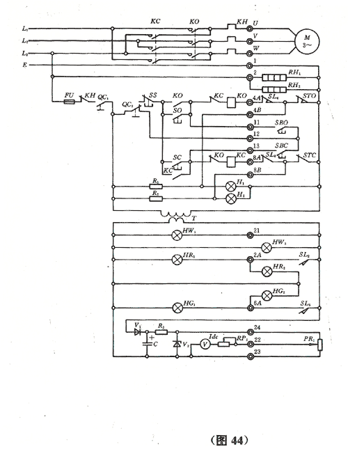
(Fig. 44) Local pushbutton scheme (1)
Fig. 45 differs from Fig. 44 in that the local buttons are mechanically interlocked rather than momentary; the local/remote selector QC2 differs accordingly and a stop button SBS is added on the actuator. Travel/torque contact count equals Fig. 42; the multi-contact torque switch of chapter 6 may also be used. In both schemes the local/remote selector sits in the control room — though it is more sensible on the actuator, so we also offer versions with the selector (lockable) on the actuator.
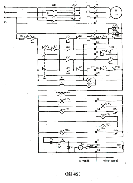
(Fig. 45) Local pushbutton scheme (2)
The integral type builds contactors, thermal relays and transformer into the actuator. Made explosion-proof it is popular in petroleum storage/transport, simplifying control-room equipment and reducing control-cable cores. In Fig. 46 components inside the dash-dot outline are in the control room, the rest on the actuator (without remote control, connecting only the power cable suffices to operate the valve). Travel/torque contacts match Fig. 42 with a large-contact NC torque switch; the Fig. 43 multi-contact type is also possible. The local/remote selector is on the actuator; local buttons are momentary or interlocked. This is the simplest integral scheme we offer.
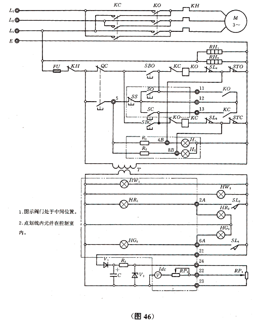
(Fig. 46) Integral basic scheme
As pipeline automation advanced, users asked for a DC 4–20 mA valve-position feedback signal. Fig. 47 shows an integral scheme with such an output. Above transformer T little changes except that all travel/torque/supply lamps use 220 V. A VOT unit is added as the main DC 4–20 mA output device, with RP1 now a precision potentiometer. Non-integral schemes can also provide DC 4–20 mA, with the VOT usually mounted on the actuator.
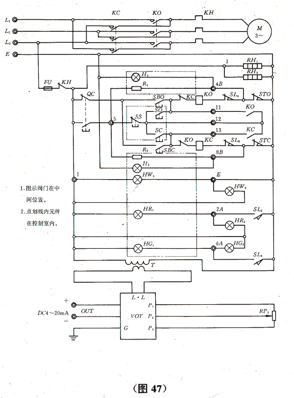
(Fig. 47) Integral scheme with DC 4–20 mA output
Our modulating actuators use dedicated three-phase or single-phase valve motors, linear or quarter-turn. They accept 4–20 mA, 0–20 mA DC or 0–10 V DC setpoints and issue corresponding signals as required. Fig. 48 shows an SMC modulating scheme: the EPC-02 can be a secondary instrument or sit on the actuator. RP1 and RP3 are precision wire-wound potentiometers — RP3 for setting, RP1 for signalling — synchronised or ganged. Several passive travel contacts are offered for the user. Fig. 48 automatically positions the valve to the DC 4–20 mA setpoint.
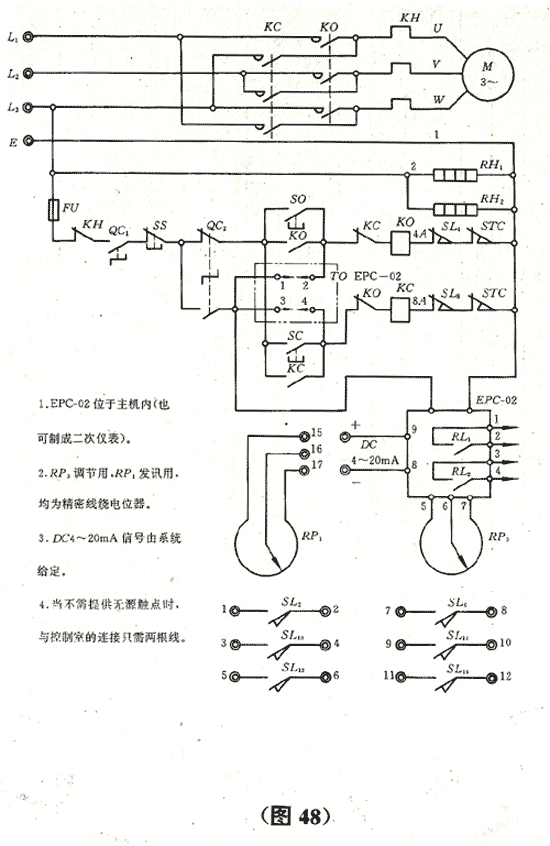
(Fig. 48) Modulating scheme
Chapter summary — This chapter outlined the basic control schemes of the SMC series, giving an overview for electrical selection during sizing.
SMC series basic parameters
| Model | Rated torque N·m | Rated thrust kN | Max. stem diameter mm | Min. gear ratio | Max. gear ratio | Unit weight kg | Flange ISO |
|---|---|---|---|---|---|---|---|
| SMC-04 | 108 | 35 | 26 | 18.47 | 90.64 | 40–45 | F10 |
| SMC-03 | 270 | 45 | 38 | 15.65 | 131.73 | 60–70 | F10 |
| SMC-00 | 491 | 89 | 50 | 11.10 | 145.50 | 100–110 | F14 |
| SMC-0 | 952 | 155 | 65 | 12.90 | 198.00 | 130–150 | F16 |
| SMC-1 | 1766 | 245 | 76 | 13.60 | 234.00 | 170–185 | F25 |
| SMC-2 | 2717 | 333 | 89 | 10.60 | 212.00 | 190–210 | F30 |
| SMC-3 | 5690 | 617 | 127 | 11.00 | 153.00 | 220–250 | F35 |
| SMC-4 | 9810 | 1078 | 127 | 13.40 | 148.00 | 270–290 | F40 |
| SMC-5 | 26487 | — | 159 | 73.00 | 228.00 | 320–350 | F48 |
Notes: 1. Values are for reference; consult our product catalogue for sizing. 2. SMC-5 itself does not take axial thrust — state this when ordering. 3. SMC-3 reaches the 5690 N·m rated torque only at certain speeds; normally 4905 N·m (depends on gear module m) — note when sizing. 4. Flanges to ISO 5210/1–5210/3-1982.
BA series manual (bevel) units basic parameters
| Model | Rated torque N·m | Rated thrust kN | Ratio | Stem bore, bronze nut mm | Stem bore, steel nut mm | Matched 1st-stage SMC unit | Flange |
|---|---|---|---|---|---|---|---|
| BA-0 | 735 | 98 | 3:1 | 55 | 45 (key 12×8) | SMC-04, SMC-03 | F16 |
| BA-1 | 1470 | 196 | 4.11:1 | 62 | 52 (key 15×10) | SMC-03, SMC-00 | F25 |
| BA-2 | 2940 | 343 | 6:1 | 85 | 70 (key 18×12) | SMC-00, SMC-0 | F30 |
| BAA-3 | 6000 | 617 | 6.1:1 | 128 | — | SMC-0, SMC-1 | F35 |
Notes: 1. Reference values only. 2. A BA-00 size exists but is not listed as unsuitable for SMC combination (small torque). 3. BAA-3 does not appear in the licensed documentation — it is our own design based on related parameters. 4. BA flanges match SMC flanges by size, but torques/thrusts differ — note when sizing. 5. Flanges to ISO 5210/1–5210/3-1982. 6. BA bevel-gear efficiency is generally not below 90%, up to 95%.
HBC series manual units basic parameters
| Model | Rated torque N·m | Ratio | Max. stem diameter mm | Weight kg | Matched 1st-stage SMC unit | Remarks |
|---|---|---|---|---|---|---|
| H0BC | 580 | 71:1 | 36 | 29 | SMC-04 | |
| H1BC | 1760 | 70:1 | 47 | 51 | SMC-04, SMC-03 | |
| H2BC | 2990 | 70:1 | 70 | 71 | SMC-03 | |
| H3BC | 7650 | 70:1 | 95 | 112 | SMC-00 | |
| H4BC | 17300 | 60:1 | 105 | 150 | SMC-0 | |
| H5BC | 26470 | 65:1 | 165 | 200 | SMC-1 | |
| H6BC | 62270 | 66:1 | 190 | 250 | SMC-2, SMC-3 |
Notes: 1. Reference values only. 2. HBC flanges are non-standard — note when sizing. 3. A high-torque size may require the next larger first-stage actuator; output speed then generally stays below 1 r/min, especially for large torques. HBC efficiency: H0BC–H3BC approx. 23%–28%; H4BC–H6BC approx. 33%–40%.
SMC series motor power and torque values
| Motor No. | Ref. power kW | Max. torque, design (kgf·m) 380V | Max. torque, guaranteed (kgf·m) | Rated torque at 20% max. | Rated torque at 40% max. | Remarks |
|---|---|---|---|---|---|---|
| 1 | 0.04 | 0.125 | 0.154 | 0.025 | 0.050 | SMC-04 |
| 2 | 0.08 | 0.250 | 0.308 | 0.050 | 0.100 | SMC-04 |
| 3 | 0.12 | 0.375 | 0.461 | 0.075 | 0.150 | SMC-04, SMC-03 |
| 5 | 0.20 | 0.630 | 0.770 | 0.130 | 0.260 | SMC-04, SMC-03 |
| 7.5 | 0.30 | 0.940 | 1.160 | 0.190 | 0.380 | SMC-04, SMC-03, SMC-00 |
| 10 | 0.40 | 1.250 | 1.540 | 0.250 | 0.500 | SMC-03, SMC-00, SMC-0 |
| 15 | 0.60 | 1.870 | 2.30 | 0.370 | 0.740 | SMC-03, SMC-00, SMC-0 |
| 25 | 1.10 | 3.120 | 3.840 | 0.620 | 1.240 | SMC-00, SMC-0, SMC-1 |
| 40 | 1.50 | 4.990 | 6.140 | 1.00 | 2.00 | SMC-00, SMC-0, SMC-1~2 |
| 60 | 2.20 | 7.490 | 9.210 | 1.50 | 3.00 | SMC-1, SMC-2, SMC-3 |
| 80 | 3.0 | 9.980 | 12.280 | 2.00 | 4.00 | SMC-2, SMC-3 |
| 100 | 4.0 | 12.480 | 15.350 | 2.50 | 5.00 | SMC-3, SMC-4 |
| 150 | 5.50 | 18.730 | 23.040 | 3.750 | 7.500 | SMC-3, SMC-4, SMC-5 |
| 200 | 7.50 | 24.960 | 30.70 | 4.990 | 9.980 | SMC-4, SMC-5 |
| 250 | 10.0 | 31.210 | 38.390 | 6.240 | 12.480 | SMC-5 |
| 350 | 13.0 | 43.690 | 53.740 | 8.740 | 17.480 | SMC-5 |
SMC series Limitorque motor current values
| No. | Motor No. | Ref. power kW | Rated torque kgf·m | Rated current A | Rated speed r/min | Stall torque kgf·m | Stall current A |
|---|---|---|---|---|---|---|---|
| 1 | 2# | 0.08 | 0.05 | 0.51 | 1400 | 0.308 | 3.570 |
| 2 | 3# | 0.12 | 0.075 | 0.66 | 1400 | 0.461 | 4.620 |
| 3 | 5# | 0.20 | 0.13 | 1.07 | 1400 | 0.770 | 7.490 |
| 4 | 7.5# | 0.30 | 0.19 | 1.34 | 1400 | 1.160 | 9.380 |
| 5 | 10# | 0.40 | 0.25 | 1.72 | 1400 | 1.540 | 12.040 |
| 6 | 15# | 0.60 | 0.37 | 3.24 | 1400 | 2.30 | 22.680 |
| 7 | 25# | 1.10 | 0.62 | 3.53 | 1400 | 3.840 | 24.710 |
| 8 | 40# | 1.50 | 1.00 | 4.39 | 1400 | 6.140 | 30.730 |
| 9 | 60# | 2.20 | 1.50 | 5.93 | 1400 | 9.210 | 41.510 |
| 10 | 80# | 3.00 | 2.00 | 7.79 | 1400 | 12.280 | 54.530 |
| 11 | 100# | 4.00 | 2.50 | 10.59 | 1400 | 15.350 | 74.130 |
| 12 | 150# | 5.50 | 3.75 | 13.10 | 1400 | 23.040 | 91.70 |
| 13 | 200# | 7.50 | 4.99 | 17.20 | 1400 | 30.70 | 120.40 |
| 14 | 250# | 10.00 | 6.24 | 22.23 | 1400 | 38.390 | 155.610 |
| 15 | 350# | 13.00 | 8.74 | 27.80 | 1400 | 53.740 | 194.60 |
Starting efficiency at different gear ratios
| Model | Gr.1 ratio | Gr.1 eff. | Gr.2 ratio | Gr.2 eff. | Gr.3 ratio | Gr.3 eff. | Gr.4 ratio | Gr.4 eff. | Gr.5 ratio | Gr.5 eff. |
|---|---|---|---|---|---|---|---|---|---|---|
| SMC-04 | 18.47–39.46 | 0.30 | 46.00–67.23 | 0.30 | 90.62 | 0.27 | ||||
| SMC-03 | 15.65–28.24 | 0.48 | 31.70–70.20 | 0.33 | 72.38–131.73 | 0.23 | ||||
| SMC-00 | 14.64–28.70 | 0.45 | 30.71–111.80 | 0.33 | 110.60–205.40 | 0.24 | ||||
| SMC-0 | 12.86–25.20 | 0.45 | 25.71–93.60 | 0.30 | 96.67–150.80 | 0.25 | 155.00–241.80 | 0.20 | ||
| SMC-1 | 13.91–26.25 | 0.45 | 27.82–87.50 | 0.30 | 90.67–170.00 | 0.23 | 178.25–232.50 | 0.20 | ||
| SMC-2 | 10.86–26.19 | 0.45 | 27.03–85.00 | 0.33 | 87.66–155.00 | 0.23 | 158.40–220.00 | 0.20 | ||
| SMC-3 | 11.05–27.77 | 0.55 | 25.74–43.00 | 0.50 | 35.88–110.19 | 0.33 | 98.45–153.19 | 0.27 | 138.18–215.00 | 0.23 |
| SMC-4 | 10.13–32.30 | 0.55 | 33.62–48.45 | 0.50 | 51.80–124.95 | 0.33 | 131.82–147.90 | 0.30 | 152.15–219.30 | 0.30 |
Actuator/gate-valve selection guide (for reference)
| Pressure MPa \ DN | 15 | 20 | 25 | 32 | 40 | 50 | 65 | 80 | 100 | 125 | 150 | 200 | 250 | 300 | 350 | 400 | 450 | 500 | 600 | 700 | 800 | 900 | 1000 | 1200 | 1400 | 1600 | 1800 | |
|---|---|---|---|---|---|---|---|---|---|---|---|---|---|---|---|---|---|---|---|---|---|---|---|---|---|---|---|---|
| 1.0 | 2.5 | 5 | 5 | 10 | 10 | 15 | 15 | 20 | 30 | 30 | 45 | 45 | 60 | 60 | 60 | 90 | 120 | 120 | ||||||||||
| 2.5 | 2.5 | 5 | 10 | 10 | 15 | 15 | 20 | 20 | 30 | 30 | 45 | 45 | 60 | 60 | 60 | 90 | 90 | 120 | 180 | 250 | 250 | |||||||
| 6.0 | 2.5 | 5 | 10 | 10 | 15 | 15 | 20 | 20 | 30 | 30 | 45 | 45 | 60 | 60 | 60 | 90 | 120 | 120 | 180 | 180 | ||||||||
| 10 | 2.5 | 5 | 10 | 10 | 10 | 15 | 15 | 15 | 20 | 20 | 30 | 30 | 45 | 60 | 60 | 60 | 90 | 120 | 120 | 180 | 250 | 250 | ||||||
| 16 | 2.5 | 5 | 10 | 10 | 15 | 20 | 20 | 20 | 30 | 30 | 45 | 90 | 120 | 120 | 180 | |||||||||||||
| 25 | 2.5 | 5 | 5 | 10 | 10 | 15 | 20 | 20 | 20 | 30 | 30 | 60 | 90 | 120 | 120 | 180 | 250 | 500 | 500 | |||||||||
| 40 | 2.5 | 5 | 5 | 10 | 10 | 15 | 20 | 20 | 30 | 30 | 45 | 60 | 90 | 120 | 180 | |||||||||||||
| 64 | 5 | 5 | 5 | 5 | 10 | 10 | 10 | 20 | 20 | 30 | 30 | 60 | 90 | 90 | 120 | 180 | 180 | 250 | 500 | 800 | ||||||||
| 100 | 5 | 5 | 5 | 10 | 10 | 15 | 20 | 20 | 30 | 45 | 60 | 90 | 120 | 180 | 250 | 500 | 500 | 800 | ||||||||||
| 160 | 5 | 10 | 10 | 15 | 15 | 20 | 20 | 30 | 30 | 60 | 90 | 120 |
Actuator/globe-valve selection guide (for reference)
| Pressure MPa \ DN | 15 | 20 | 25 | 32 | 40 | 50 | 60 | 80 | 100 | 125 | 150 | 200 | |
|---|---|---|---|---|---|---|---|---|---|---|---|---|---|
| 25 | 5 | 10 | 10 | 20 | 20 | 30 | 45 | 60 | |||||
| 40 | 5 | 10 | 10 | 20 | 30 | 45 | 60 | 90 | |||||
| 64 | 5 | 10 | 10 | 20 | 30 | 45 | |||||||
| 100 | 5 | 10 | 10 | 20 | 30 | 45 | 60 | ||||||
| 160 | 5 | 10 | 10 | 20 | 30 | 30 | 45 | 90 | 120 | 180 | |||
| 320 | 5 | 10 | 20 | 30 | 45 | 45 | 90 | 120 | 200 | 400 |
Actuator/ball-valve selection guide (for reference)
| Pressure MPa \ DN | 50 | 60 | 80 | 100 | 125 | 150 | 200 | 250 | 300 | 350 |
|---|---|---|---|---|---|---|---|---|---|---|
| 16 | 5 | 5 | 10 | 20 | 30 | 50 | 100 | 250 | 400 | 600 |
| 40 | 5 | 10 | 20 | 45 | 75 | 120 | 300 | 600 | 1000 | 1500 |
| 64 | 10 | 20 | 30 | 60 | 120 | 200 | 500 | 1000 | 1500 | 2500 |
Actuator/butterfly-valve selection guide (for reference)
| Pressure MPa \ DN | 100 | 125 | 150 | 200 | 250 | 300 | 350 | 400 | 450 | 500 | 600 | 700 | 800 | 900 | 1000 | 1200 | 1400 | 1600 | 1800 |
|---|---|---|---|---|---|---|---|---|---|---|---|---|---|---|---|---|---|---|---|
| 2.5 | 12.5 | 12.5 | 12.5 | 12.5 | 25 | 25 | 50 | 50 | 100 | 100 | 100 | 200 | 200 | 400 | 400 | 400 | 600 | 900 | 2500 |
| 6 | 25 | 25 | 25 | 50 | 100 | 100 | 100 | 200 | 200 | 400 | 400 | 400 | 800 | 2000 | 2000 | 2500 | 3000 | ||
| 10 | 25 | 25 | 25 | 50 | 100 | 200 | 200 | 250 | 400 | 400 | 800 | 1000 | 1600 | 2500 | |||||
| 16 | 25 | 25 | 25 | 25 | 50 | 50 | 180 | 180 | 200 | 200 | 400 | 400 | 400 | (wafer type) | (wafer type) | (wafer type) | (wafer type) | (wafer type) |
Note: the values in the selection guides are the motor frame numbers (see the motor power and torque table) and are for reference only; the product catalogue prevails.






