The Fisher DVC2000 digital valve controller (smart positioner) is a workhorse of Emerson's Fisher brand, built as a modular unit for easy disassembly and maintenance. Starting from the hardware structure, this article explains the working principle and closed-loop feedback, then walks through complete field commissioning — travel calibration, tuning and key parameter configuration — plus three high-frequency faults with causes and remedies. It complements our earlier DVC2000 quick-setup article.
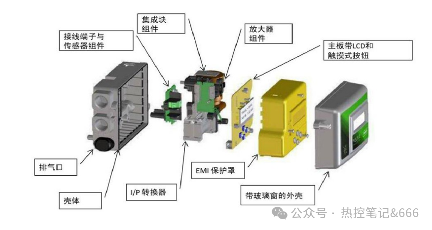
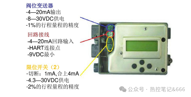
The DVC2000 mainly consists of:
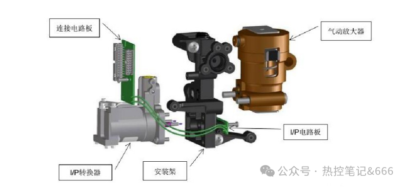
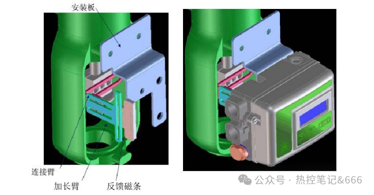
💡 Key point: the DVC2000 uses non-contact magnet-strip feedback instead of a mechanical linkage. Ensure the strip and sensor board are correctly aligned at installation; a loose mounting directly causes inaccurate position feedback.
The DVC2000 receives the 4–20 mA control signal from the control system; the internal I/P converter turns it into a pneumatic pressure signal, the pneumatic amplifier boosts the supply air, and the output drives the control valve actuator.
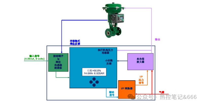
The built-in position sensor continuously reads the actual valve travel, forming an inner closed-loop feedback; the actuator casing pressure is measured as well.
Language selection: press all four arrow keys together for 3 seconds, then use the up/down keys to choose from seven languages, and confirm with a right-key press.
Valve action (air-to-open / air-to-close) setting:
| Air-to-open (FC) | Command | Valve position | LCD | Feedback |
|---|---|---|---|---|
| — | 4 mA | 0% | 0% | 4 mA |
| — | 20 mA | 100% | 100% | 20 mA |
| Air-to-close (FO) | Command | Valve position | LCD | Feedback |
| — | 4 mA | 100% | 100% | 20 mA |
| — | 20 mA | 0% | 0% | 4 mA |
Prerequisites: valve free of mechanical sticking, air supply pressure normal, wiring correct.
Purpose: let the positioner learn the valve's actual 0% (closed), 50% (mid) and 100% (open) positions.
⚠️ During calibration all keys are disabled — do not interrupt; wait for the automatic sequence to finish, then confirm and save with the right key.
Gain codes: C slowest → M fastest; "L" is the usual field default. The goal is accurate valve response without oscillation.
Most parameters are factory-preset; only the key items need adapting to the valve:
| Main menu | Submenu | Setting | Notes |
|---|---|---|---|
| Quick Setup | — | — | quick search of 0%, 100%, 50% |
| Travel Calibration | — | Auto, Manual | search 0%, 100%, 50% |
| Tuning | — | Auto, Manual | manual if oscillating; tuning value: C–M |
| Detailed Setup | Zero control signal | Valve opens / closes | per valve actuator action (air-to-close or air-to-open) |
| Detailed Setup | Pressure units | PSI, KPA, BARKPA, BAR | — |
| Detailed Setup | Low input range value | 4 mA | up/down keys, 4–19 mA |
| Detailed Setup | High input range value | 20 mA | up/down keys, 5–20 mA |
| Detailed Setup | Input characteristic | Linear, user-defined, quick-open, equal-percentage | — |
| Detailed Setup | Position transmitter output 4 mA | Valve opens / closes | for air-to-close the input and feedback values are reversed |
| Detailed Setup | Switch 1 trip point | 10% | increase/decrease with up/down keys |
| Detailed Setup | Switch 1 made | below 10% | increase/decrease with up/down keys |
| Detailed Setup | Switch 2 trip point | 90% | increase/decrease with up/down keys |
| Detailed Setup | Switch 2 made | above 90% | increase/decrease with up/down keys |
| Analog input calibration | — | — | — |
| Position transmitter calibration | — | — | — |
| Local control | — | Analog, Manual | — |
The valve can be driven manually from the positioner panel for maintenance:
After maintenance, always switch back to Analog mode to restore remote control.
Fault 1: valve does not move at all on remote signal
Fault 2: large deviation between DCS command and position feedback
Fault 3: sluggish valve, slow stroking
💡 Tip: if parameters are accidentally changed, the positioner keeps the most recent configuration and can restore it — no need to start commissioning from scratch.
Related reading: Fisher DVC2000 Digital Valve Controller: Quick Setup, Travel Calibration & Troubleshooting; Smart Valve Positioners — Universal Commissioning Workflow & Cross-Brand Troubleshooting






