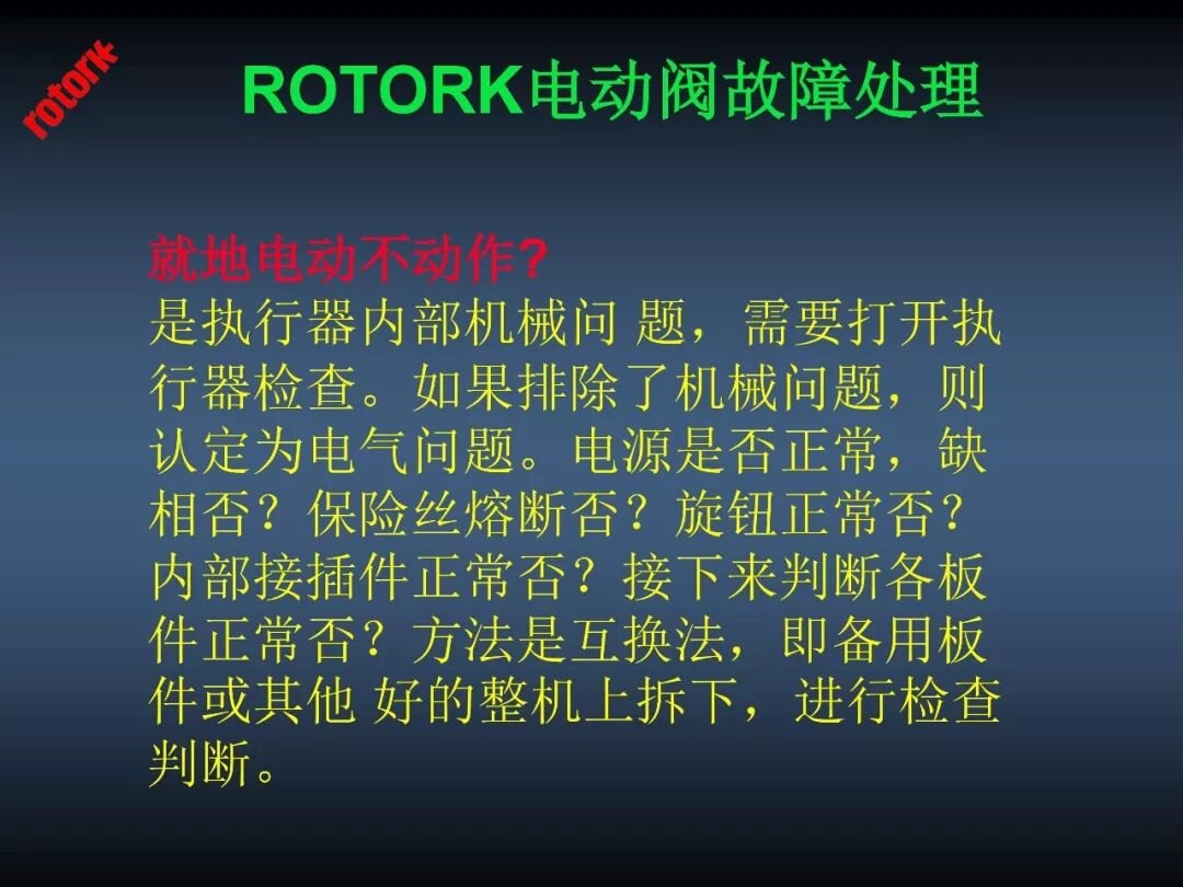
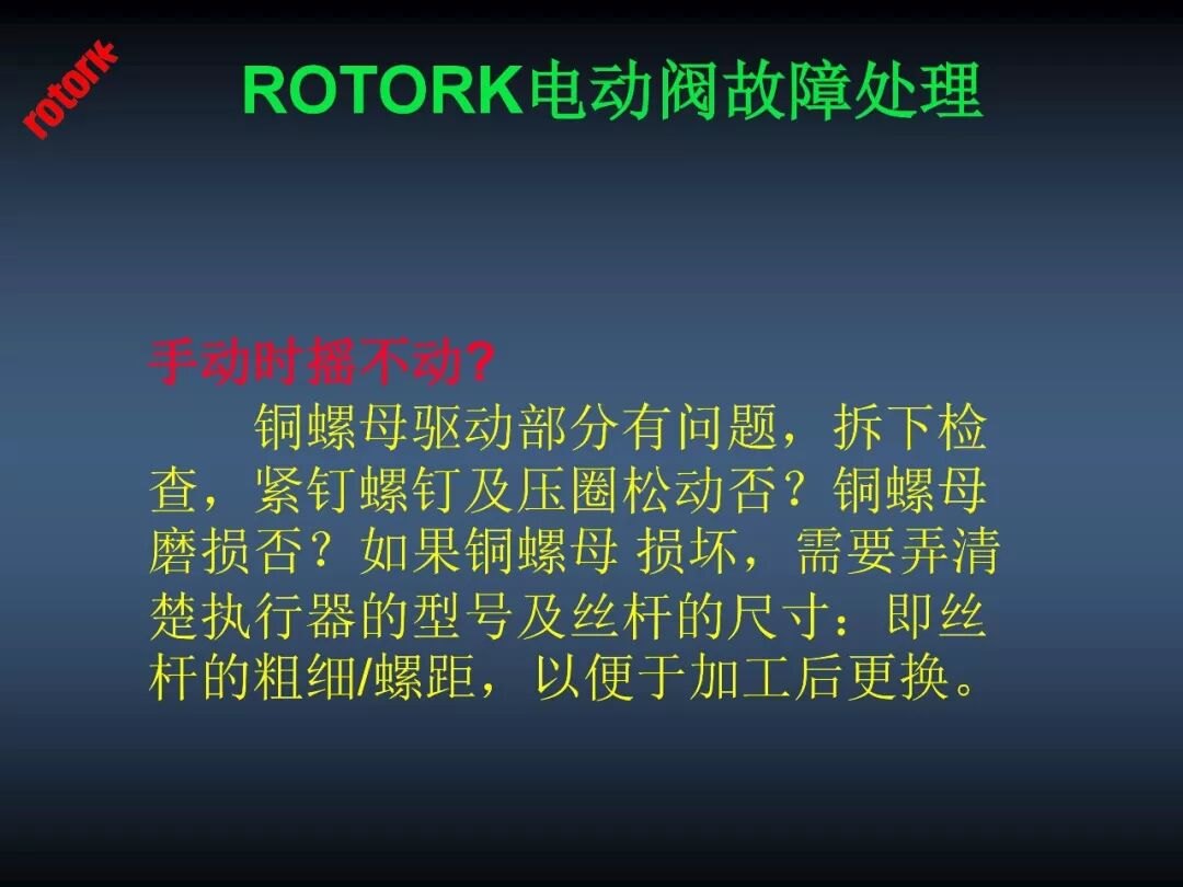
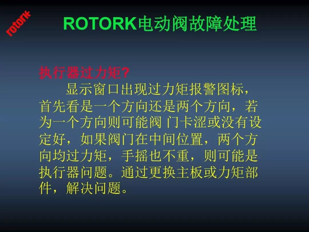
Field wiring, commissioning and fault handling are the two pages of the Rotork manual that power-plant instrument crews consult most. This reference combines: Part 1 — a maintenance/fault-handling training deck (actuator cutaway, setting-tool keys, commissioning steps with photos); Part 2 — handwheel-setter commissioning with the full parameter menu (stroke/torque/limit/contacts/signal) and 28 common faults with fixes. Figures and text are reproduced faithfully.
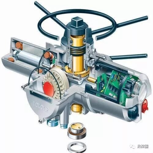
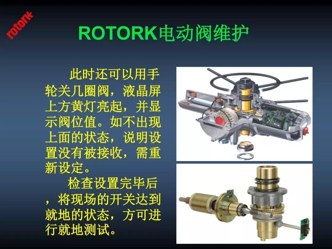
Cutaway: motor drives the worm stage through the clutch; three-key spline output drives the valve; counter and position-feedback boards provide indication and 4–20 mA.
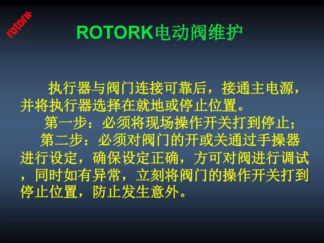
Setting-tool keys: down = next function; right = next function horizontally; -- = decrease; + = increase; enter = confirm; three-key = open; work-key = close. Slides below (always set the local/remote switch to STOP before commissioning, and pre-set the valve open/close with the handwheel).
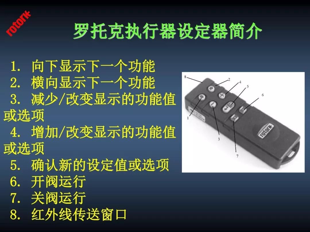
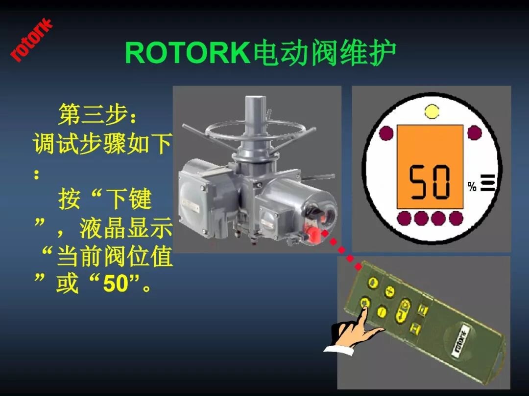
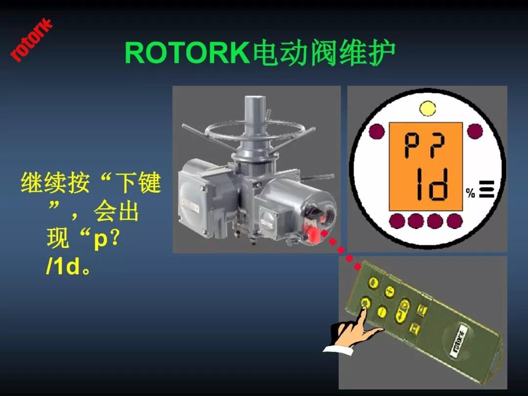
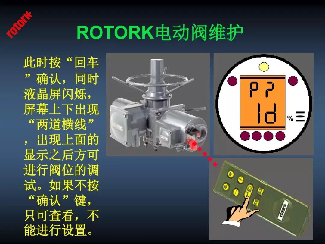
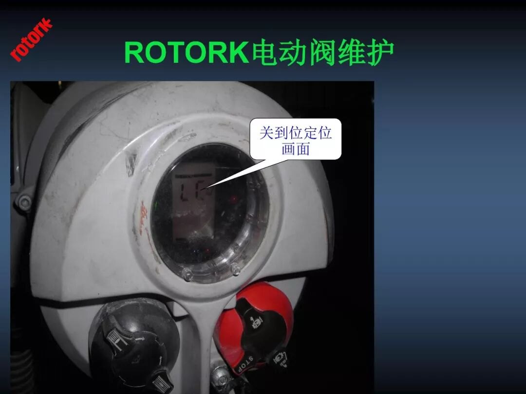
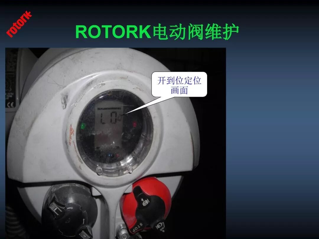
Setting-tool keys: (1) down = next function; (2) right = next horizontally; (3) -- decrease/change; (4) + increase/change; (5) enter = confirm; (6) three-key = open; (7) work-key = close. The infrared setter handles torque, limit and other settings; all adjustments are stored in non-erasable memory. Two levels — primary and secondary; primary must be set first.
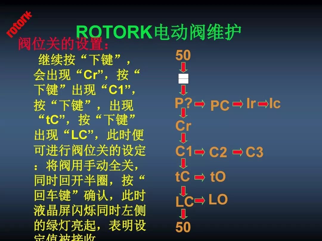
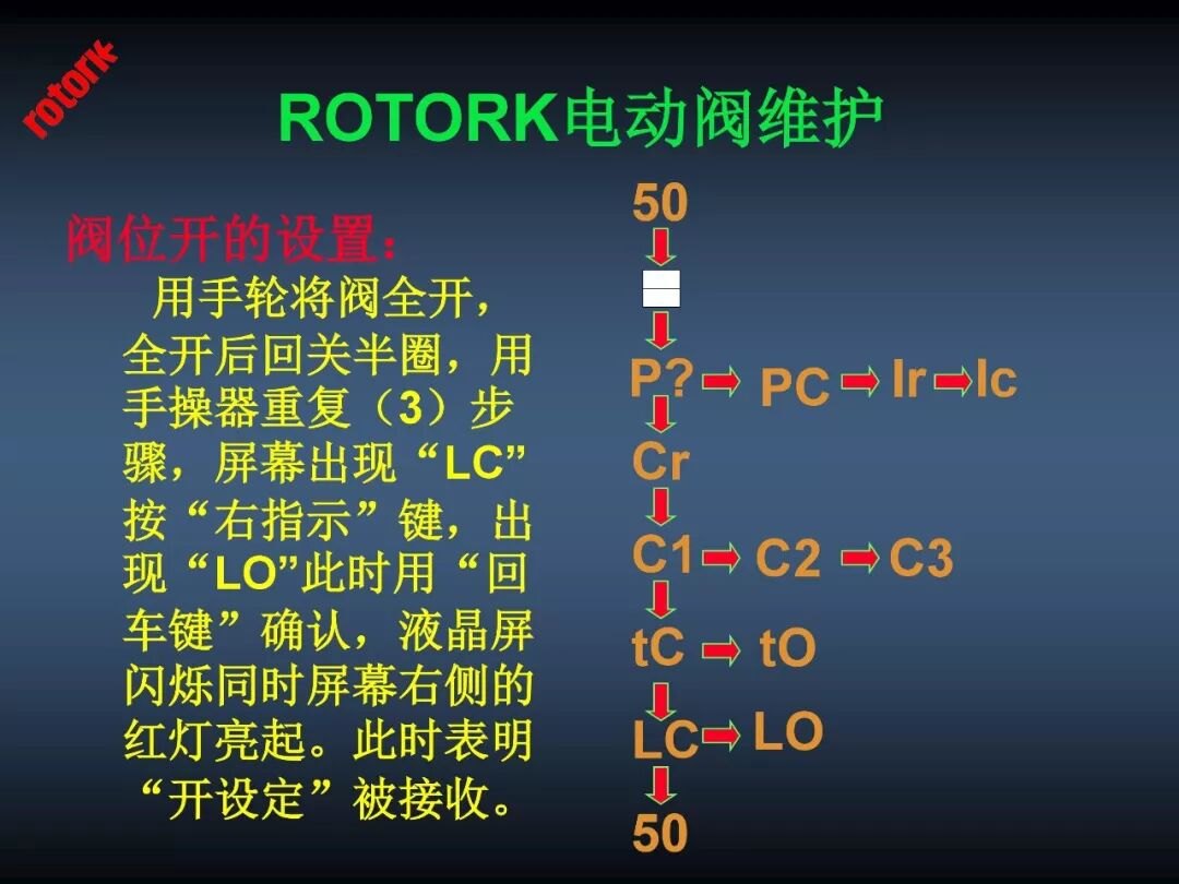
Stroke setting (primary includes stroke and feedback): switch to local and follow the menu: 00 ↓ – ↓ P? ↓ Cr → secondary ↓ C1 → C2 → C3 ↓ tC → tO ↓ LC → LO ↓ 00.
Secondary functions: in local, from Cr set the parameters per the table below.
| Parameter | Function | Setting |
|---|---|---|
| P? | Commissioning password | |
| Cr | Program branch point | |
| C1 | Closing direction | (C) clockwise-close, (A) reverse |
| C2 | Closing mode | (Ct) torque-close, (CL) limit-close |
| C3 | Opening mode | (Ot) torque-open, (OL) limit-open |
| tC | Closing torque | 40–99% of rated |
| tO | Opening torque | 40–99% of rated |
| LC | Close limit | Hand-close snug, back half a turn |
| LO | Open limit | Turn to full open, back half a turn |
| 00 | Valve position |
Contact and signal parameters:
| Parameter | Function | Setting |
|---|---|---|
| S1–S4 function | Contact function | CL close-limit, OP open-limit |
| S1–S4 contact type | NO/NC | NO normally open, NC normally closed |
| OF | Remote proportional control | ON enabled |
| 0d | Remote control source | dO remote proportional |
| F1 | Signal type | I current signal |
| Fr | Signal range | 4–20 mA |
| FL | Valve low-point signal | 4 mA from control room confirms low |
| FH | Valve high-point signal | 20 mA confirms high |
| Fd | Dead band | 15 (=1.5%) |
| Ft | Inhibit time | >5 seconds required |
| FA | Signal-loss response | ON respond |
| FF | Action after signal loss | SP hold |
| H1–H9 | Help screens | |
| d1→d2 | Initial options |
1. No output at the valve stem: A. check hand operation — a clutch stuck in manual makes the motor spin free; B. check the motor turns; C. if neither manual nor motor works, suspect a jammed valve; D. disconnect the valve — if not jammed, check the sleeve for seizure, stripped threads or looseness.
2. Will not stop at the set travel; stem hits the body: LC/LO lost — reset, or change torque-open/close to limit-open/close.
3. Displayed position differs from actual: Reset limits; if it drifts again after a few strokes, replace the counter board.
4. Runs but no position indication: Counter magnet or counter board failed; no 4–20 mA on 22/23 — replace the (servo+) feedback board.
5. Hunting in remote modulating: Raise dead-band Fd; if hunting persists above 20, replace the (servo+) feedback board; if still, fit a slower motor or widen the sleeve/stem thread pitch.
6. Dead in remote and local, or runs one way only: Check the clutch is not stuck and the motor is intact; check wiring and phase balance.
7. Dead in remote and local: Measure windings — thermal protection/open electromagnetic feedback, motor burned.
8. Dead both modes; setter shows H1 torque-switch open / H6 no electromagnetic feedback: (Solid-state) relay has no output — replace relay control board or power board.
9. Three-phase supply trips instantly: Relay control board fault or burned motor coils.
10. Fuse blows at 400 V+ supply, again after replacement: With the rectifier block normal, check the power-transformer primary resistance — replace power board or transformer.
11. Backlight off: With supply normal, check fuse or the main-board power plug.
12. Fine unloaded but stops at ~40% closing under load even at torque 99; handwheel closes fully: Worked when new, degrades — fit one size larger actuator.
13. Manual OK, will not switch to motor: Clutch spring stuck toward manual — remove handwheel, release, reassemble.
14. Dead both modes, open/close lamps flashing: Battery low — settings lost at power loss; replace battery and re-set.
15. Runs but no position feedback; 22/23 gives 1–3 mA: Re-set; if ineffective replace the (servo+) feedback board; if the loop is fine disconnected, the external cable is at fault.
16. Torque trips during travel; raising settings does not help: Check for dried lubricant or a jammed valve.
17. Valve will not close tight: Reset travel limits; if unresolved, the valve is at fault.
18. Sets and runs fine but will not pass a position: Jammed valve or gearbox mechanical stop reversed — check by hand and re-set.
19. Motor vibrates, starts and stops, slow: With the clutch OK, replace the (solid-state) relay and re-check.
20. Position and feedback frozen; LO/LC cannot be set: Main board failed — replace.
21. New power board runs hot at the rectifier: Some components on the main board burned — replace main board.
22. Dead both modes; will not accept settings; position shows in manual: Replace main board and relay control board; or the switch magnet is broken/missing.
23. Remote OK; local control raises alarm: Replace the local control board.
24. Remote dead, local works but position display frozen: Loose plug — reseat; still dead, replace the (servo+) feedback board.
25. Local fine; remote-close drives fully open regardless of signal; limit reset ineffective: Replace the (servo+) feedback board.
26. IQ MK2 shows valve alarm; relay trips instantly in both directions: Replace the torque sensor in the motor.
27. Backlight off or garbled symbols, three status lamps on together: Replace main board; run and end lamps on together = limit/rotation direction conflict — re-set.
28. Some alarm contacts do not switch; remote/local state not detected: Replace main board or I/O board.
Other faults mostly stem from installation, setting or operation, sometimes mixed — work through the alarm display and the H help screens one by one.
Rotork document library, 390 files (IQ/IQT manuals and wiring diagrams) · Rotork IQ series, 28 faults and fixes · First Rotork IQ3 Pro units delivered to HyNet · Motor-stall alarm: opens but will not close · 1% then 4-second pause: fault or inhibit function? · Damper re-positioning field notes
For Rotork actuators and spares submit an RFQ.

An industry resource for electric & pneumatic actuators, dampers and heaters: brand manuals, sizing guides and maintenance know-how. Global brands in, China manufacturing out.