Fig. 1 Superheater outlet temperature control system
Per site conditions the total-air feedforward was dropped. The superheat setpoint is not a constant but load-related: Fig. 1 uses first-stage pressure as the load signal, summed through a function generator with the operator's bias to form the setpoint. Because the setpoint-to-load relation differs between constant-pressure and sliding-pressure operation, two function generators are used — CLB-FX1 for constant pressure, CLB-FX2 for sliding pressure; per commissioning, the first-stage-pressure addition to the setpoint has been zeroed.
Auto/manual selection and interlocks are in Fig. 2: without MFT and above 30% load (37.5 MW), if both superheat spray-valve commands exceed 1%, the spray water block valve opens; on MFT or below 30%, any of actuator fault, control fault, bad superheater-outlet signal or bad secondary-desuperheater outlet signal forces the sprays to manual; when both spray-valve commands fall below 0.5%, the block valve closes.
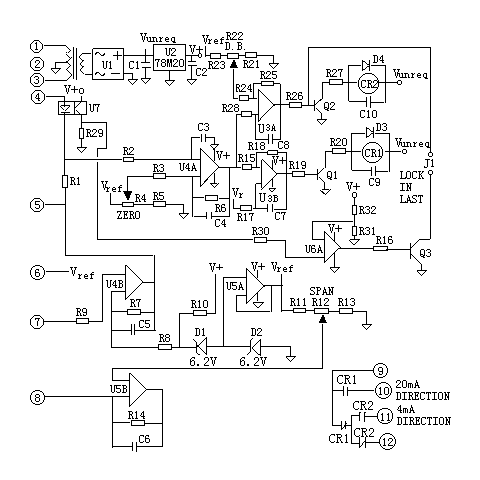
Fig. 2 Auto/manual control and interlock logic
The Limitorque actuator opens and closes the spray valve while limiting stem torque and thrust, protecting all valve operating parts against overload, mispositioning or jamming (Fig. 3).
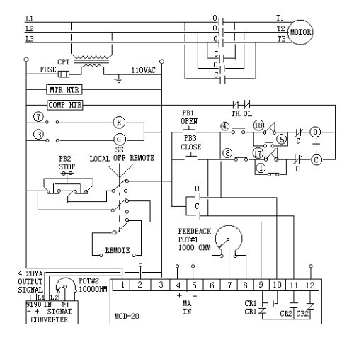
Fig. 3 L-120 actuator principle
In LOCAL mode the PB1 open and PB2 close buttons on the actuator panel operate it: pressing either energises the open or close coil, closing main-circuit contact (O) or (C) — used during commissioning and emergencies. In REMOTE mode the output relays CR1/CR2 on the servo board close control-circuit contacts (O)/(C) — these parallel PB1/PB2. In OFF, or with PB2 pressed, the 115 V AC control supply is cut and only the handwheel works. Travel switches 3 and 7 drive the panel red/green lamps; travel switches 1, 5, 4, 8 and torque switches 17, 18 serve full-open, full-close and intermediate limits; normally-closed contacts (O) and (C) provide open/close interlocking.
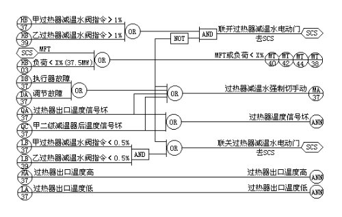
Fig. 4 MOD-20 servo board principle
In Fig. 4, after transformation, rectification, filtering and regulation, V+ powers the op-amps. The DCS command at terminals 4/5 is compared with the feedback at 7/8; the larger decides whether CR1 or CR2 energises. Span, zero and dead band adjust via potentiometers R12, R4 and R22.
Commissioning after installation:
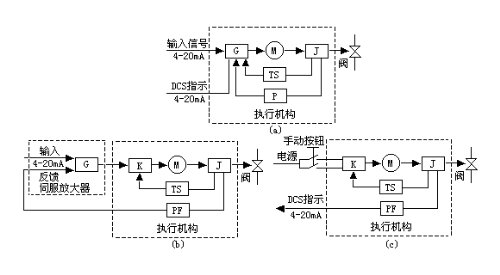
Bernard SD actuators come as modulating (a), external-servo (b) and remote-control (c) types: modulating units serve first superheat, first reheat and second reheat; the external-servo (CR-2) type serves second superheat; the remote type serves first-stage desuperheating (Fig. 5).
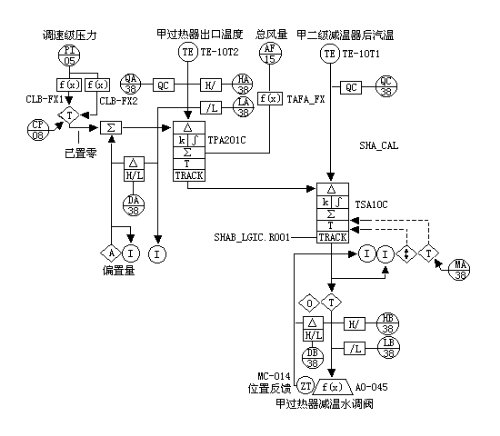
Fig. 5 Bernard SD principle (G: GAMX-2000 servo amplifier; M: motor; J: reducer; TS: torque/travel limiter; P: travel sensor potentiometer; PF: position transmitter)
Layout and wiring of motor, limit switches, servo and transmitter in the modulating unit are shown in Fig. 6.
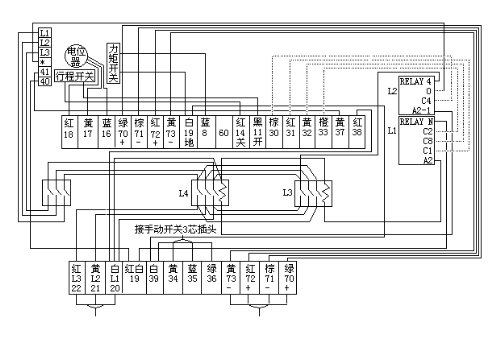
Fig. 6 Bernard SD modulating actuator principle
A bevel gear on the clutch sleeve's upper drive lug drives the gear limit switches, so the switches connect directly to the actuator output and, correctly set, track valve position in manual as in electric operation. The worm and shaft pass through two spring assemblies: when torque arises the worm moves axially against a spring; each assembly is pre-calibrated so a given compression means a given torque; the worm's motion trips the torque switch, cutting motor power. Torque switches are adjustable to pre-set torques.
Phase check: with the cam turning clockwise, press the OPEN switch with a screwdriver — the actuator must stop. If not, cut power immediately, swap any two supply phases and recheck. Clockwise cams use the CLOSE switch the same way.
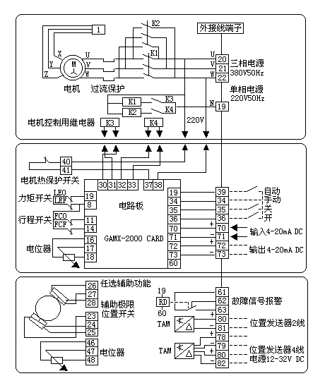
Fig. 7 Bernard SD wiring principle
Before replacing the L-120 with the Bernard SD in the steam-temperature control system, compare how the two models handle the same duties (spray-water modulating service) — this is why the control circuits had to be redesigned:
| Aspect | Limitorque L-120 | Bernard SD |
|---|---|---|
| Local operation | Panel pushbuttons: PB1 open, PB2 close — coils energize the (O)/(C) contacts in the power circuit | Selector to MAN; operate via the local manual potentiometer P1 |
| Remote operation | Servo-board relays CR1/CR2 close the (O)/(C) control contacts, wired in parallel with PB1/PB2 | Servo amplifier GAMX-2000 (G) drives the motor |
| Position feedback | 1 kΩ coaxial potentiometer (≈500 Ω at 50% valve travel) | Travel sensor P (potentiometer) + position transmitter PF |
| Travel / torque protection | Limit switches 1, 5, 4, 8 for end and intermediate limits; torque switches 17, 18 for seating and jam protection | Gear-driven limit switch directly coupled to the output — synchronized with valve position in manual and electric modes once set; separate torque/travel limiter TS |
| Dead band & full-scale | — (not covered in the source) | P3 multi-turn potentiometer sets dead band; P2 full-scale potentiometer trimmed against the LED |
| Status indication | Panel red (R) / green (G) lamps | Red / green LEDs |
| Torque-check test | Torque limit switches have graduated dials (for seating/jam duty, normally left as set) | Press the torque switch manually while running: red LED flashes and the actuator stops; protection auto-resets on reverse or power-off |
Note: nameplate data (rated torque, output speed) for both models is not covered by the source. The Bernard SD series is discontinued and its official literature is no longer readily available — refer to the unit manual for selection data.
In service the servo sometimes fails to trigger open or close, or the small relay contacts burn from arcing. Beyond replacing spares, try: if the servo board fails, disconnect the two small black plugs (to the small relays) and wire the servo's two switch lines to the upper terminals of the main contactor coil, disconnecting its original 220 V (powered contact). If the servo output is a dry contact, keep the original 220 V line to the coil, wire the servo switch lines to the lower terminals, and earth to terminal 19.
Need Limitorque (L-120/MX) or Bernard actuators, spare parts or retrofit support? Submit an RFQ.

An industry resource for electric & pneumatic actuators, dampers and heaters: brand manuals, sizing guides and maintenance know-how. Global brands in, China manufacturing out.