A customer sends a gearbox photo — which series is it, and can our electric actuator drive it? Our gearbox line has 8 series, each with a distinct look. This article shows one outline drawing per series with identification points, duty and torque range, for at-a-glance matching. Full selection tables and dimensions: gearbox catalogue download.
How to recognise: horizontal worm housing, output flange facing up (valve/actuator side), small input flange on the side, foot-mounted. Duty: 90° quarter-turn valves, direct-coupled actuators. Torque 250–600,000 N·m (GS50.3–GS600); R versions add a second input stage (ratios up to 2,720).
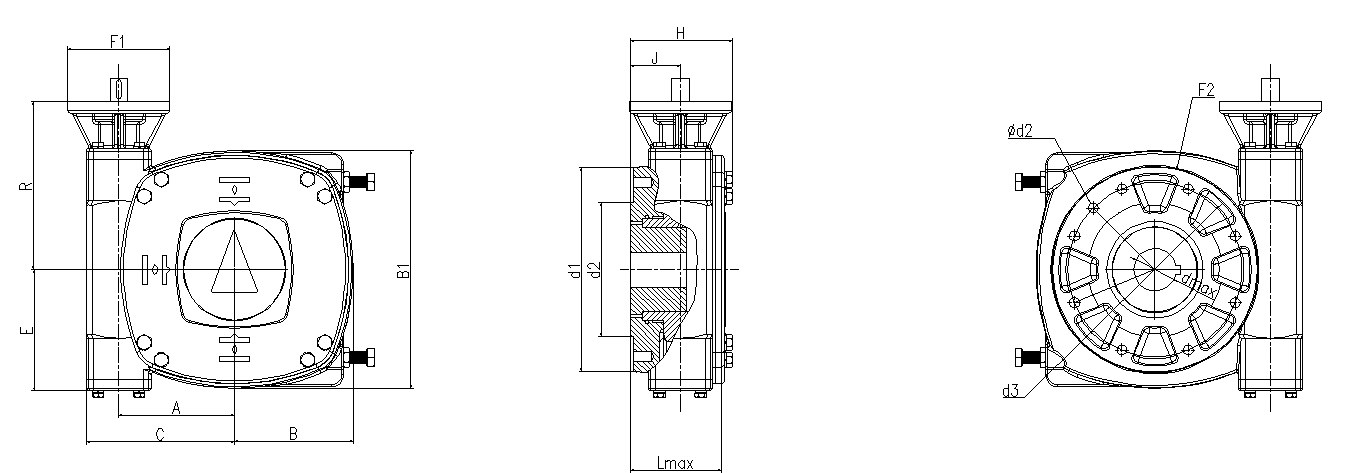
GS series quarter-turn worm gearbox outline (outline drawing from the SJMC gearbox catalogue)
Recognise: same worm housing as GS but with feet/bracket holes and keyed output shaft — not flange-up. Duty: lever/linkage drive without a direct flange. GF50.3–GF250.3 (+R), input flanges F07–F25.
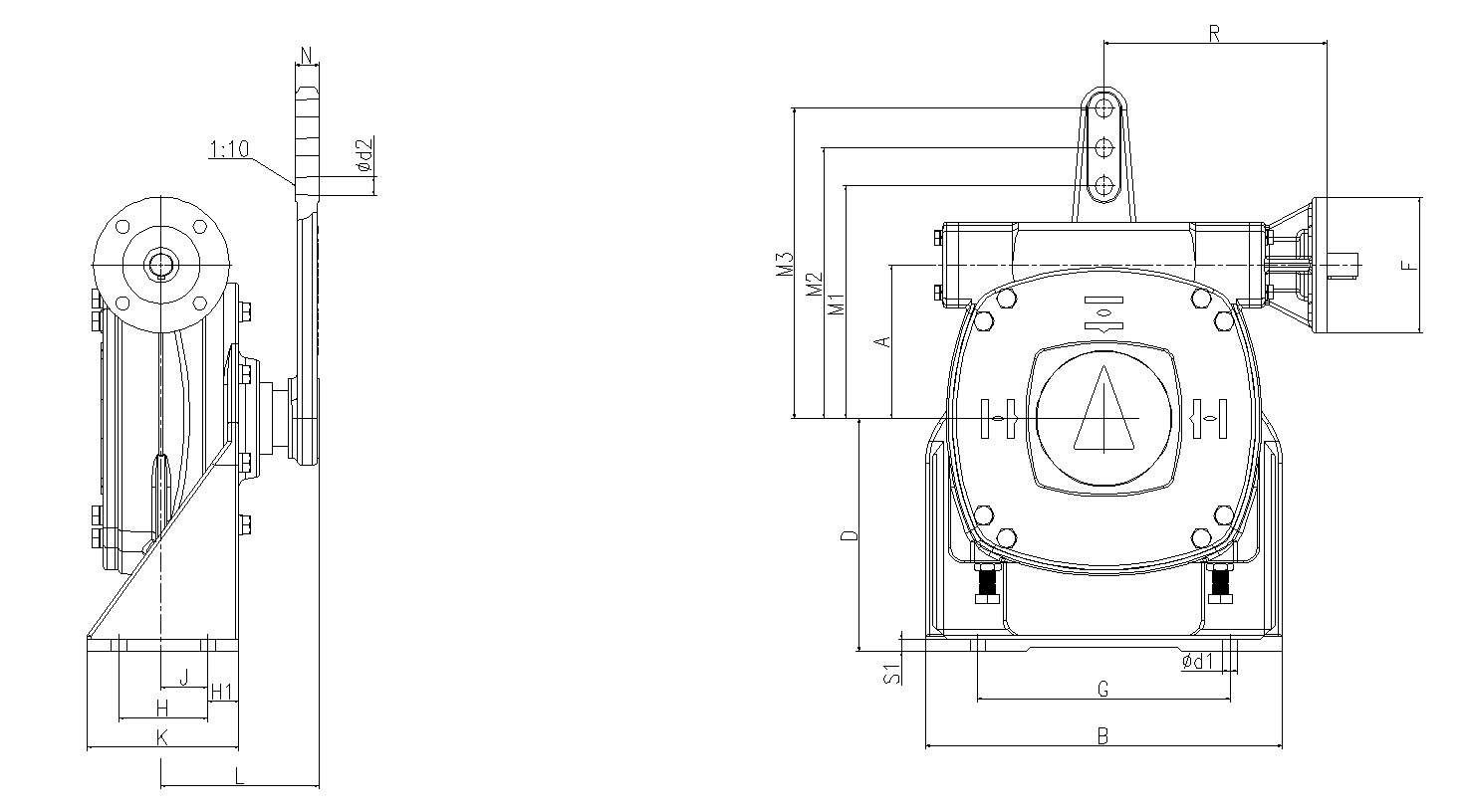
GF series bracket-type worm gearbox outline (outline drawing from the SJMC gearbox catalogue)
Recognise: GS-like but much larger, big output flange, twin bearing blocks. Duty: high-torque quarter-turn. IW3–IW14 (R: ratios 128–2,564), torque 600–500,000 N·m; IW bracket dimensions made to order.
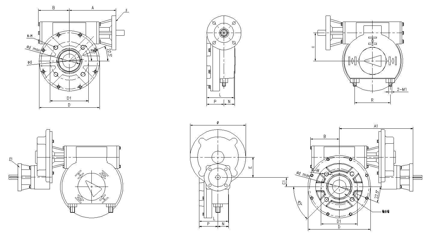
IW series large worm gearbox outline (outline drawing from the SJMC gearbox catalogue)
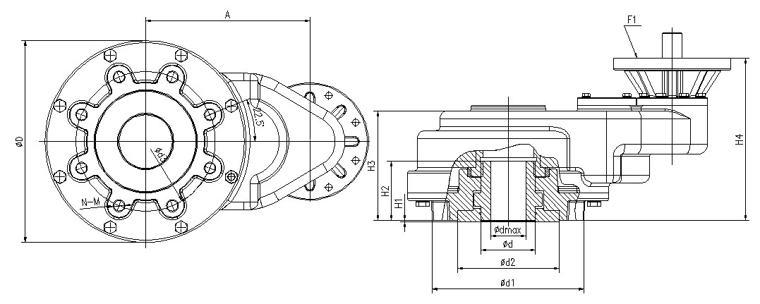
Recognise: bevel gear reversing head + tall protective cover + output valve-stem bronze nut — an upright reverser, not a horizontal worm box. Duty: drives gate/globe valves from multi-turn actuators or handwheel stations (stem nut G2″–M160×3). Torque 600–15,000 N·m (GK14.6–GK40.2, R versions).
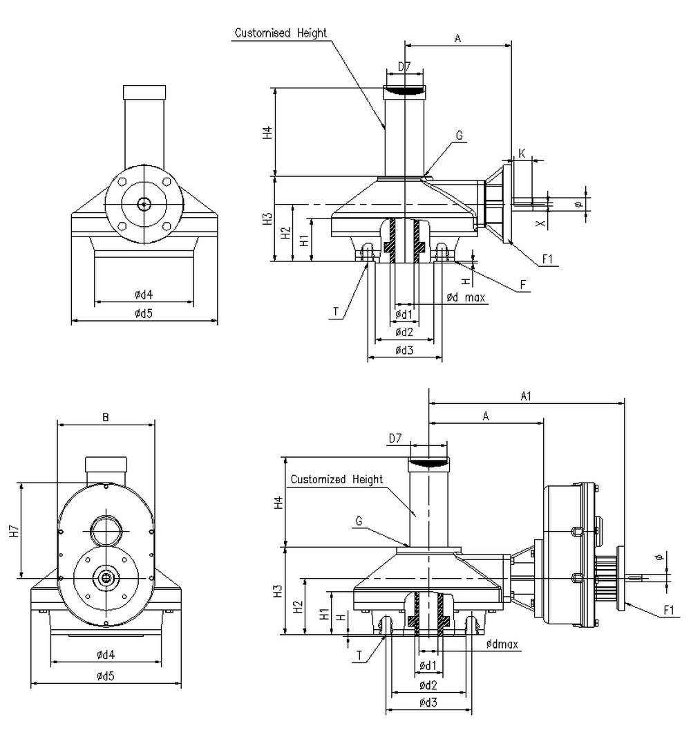
GK series bevel multi-turn gearbox outline (outline drawing from the SJMC gearbox catalogue)
Recognise: long horizontal push-rod with trapezoidal thread (Tr32–Tr40, left-hand), flanges at both ends — "a long barrel with a screw". Duty: mates a multi-turn actuator to convert torque into thrust. Thrust 11.5–217 kN (LE12.1–LE200.1, stroke 50–500 mm).
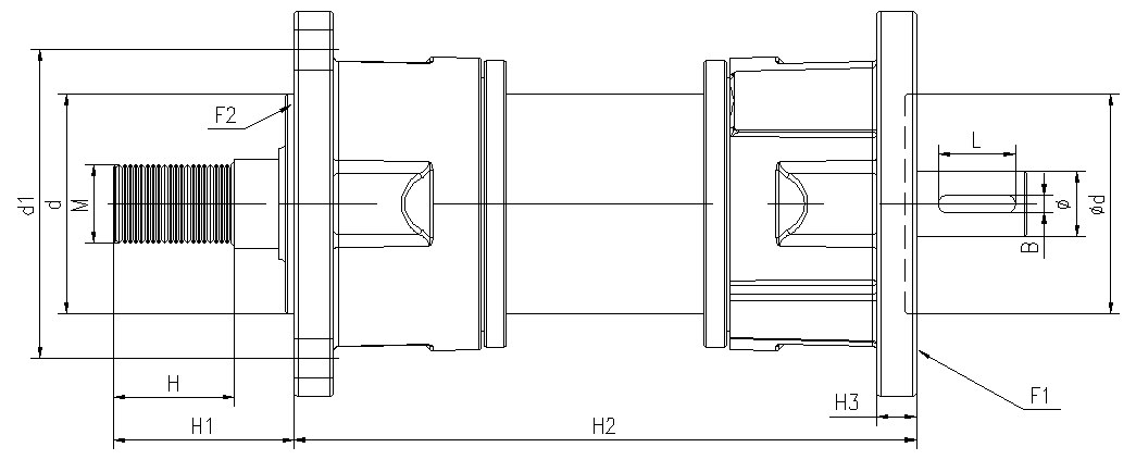
LE series thrust unit outline (outline drawing from the SJMC gearbox catalogue)
Recognise: a link with ball ends both sides + connecting tube + adjuster nut; straight-shank and tapered-shank pin versions, 0–110 mm adjustment. Duty: connects quarter-turn actuator levers to valve/damper levers. Torque 100–20,000 N·m (QJ-10–QJ-2000).
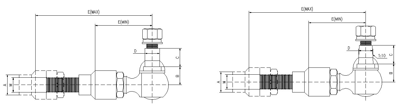
QJ ball-joint linkage outline (straight / tapered shank) (outline drawing from the SJMC gearbox catalogue)
Recognise: large-flange horizontal worm housing, ratios 2–36 (low ratio, high transmission), output flange from F10. Duty: 300–15,000 N·m quarter-turn (GZ160.3–GZ45). Note: the "GZ ball joint" in Bernard brochures is a different product with the same code — match by picture, not by name.
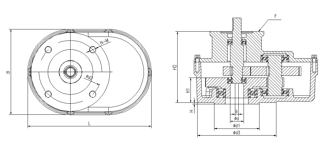
GZ series worm gearbox outline (outline drawing from the SJMC gearbox catalogue)
Recognise: cylindrical multi-stage spur-gear barrel (not worm), dual input/output flanges. Duty: multi-turn torque amplification. BST1.5–BST20, torque 1,500–20,000 N·m, ratios 2–8 (some steps unclear in the original; see the catalogue).
BST series spur multi-turn gearbox outline (outline drawing from the SJMC gearbox catalogue)
| Series | Look | Duty | Torque N·m |
|---|---|---|---|
| GS | Horizontal worm, output flange up | Direct-mount quarter-turn | 250–600,000 |
| GF | GS with feet/bracket | Lever/linkage duty | — |
| IW | Large horizontal worm | High-torque quarter-turn | 600–500,000 |
| GK | Upright reverser + stem nut | Gate/globe multi-turn | 600–15,000 |
| LE | Long push-rod + trapezoidal screw | Linear thrust | 11.5–217 kN thrust |
| QJ | Double-ball-head link | Actuator-to-damper lever link | 100–20,000 |
| GZ | Large-flange horizontal worm (low ratio) | Quarter-turn | 300–15,000 |
| BST | Cylindrical spur-gear barrel | Multi-turn torque boost | 1,500–20,000 |
Connection flanges cover F03–F60 (ISO 5211 up to oversize); see the catalogue download for full tables.
Gearbox catalogue download: 8-series selection tables & dimensions (CN/EN PDF) · Actuator braking methods · Damper ordering parameters
Unsure which gearbox your photo shows? Send it with an RFQ — same-day reply.
Outline drawings from the SJMC gearbox catalogue (19 pages, downloadable on this site); figures per the catalogue selection tables.

An industry resource for electric & pneumatic actuators, dampers and heaters: brand manuals, sizing guides and maintenance know-how. Global brands in, China manufacturing out.