FGD-system dampers must achieve "zero leakage" during maintenance isolation — how is it designed, and why does it often fail in the field? This article walks through the three elements of zero-leakage design (mechanical seal + double-louver sealing-air passage + duty/standby sealing-air system), the three classes of field leakage causes (manufacturing, commissioning, sealing-air system), and the corresponding corrective actions. Pair with why sealing-air systems matter and the 8 ordering parameters.
| Element | Design points |
|---|---|
| Mechanical seal | Seal strips + press plates + fasteners form an elastic seal structure with the vanes; strip elasticity compensates flatness errors between vanes — small gaps, reliable sealing |
| Sealing-air passage | Double-louver vanes + frame form a sealed-air cavity, keeping smooth sealing-air flow between vanes and between vanes and frame |
| Sealing-air system | Two fans (one duty, one standby) + one heater; the system is sized per the damper’s actual duty |
Body design plus the sealing-air system together achieve 100% flue-gas isolation. In a double-louver damper the inter-vane chamber is charged with sealing air 500 Pa above the flue-gas pressure, giving a no-leakage isolation class (single-louver dampers without sealing air are designed to 99% sealing efficiency); design ΔP ≥8,000 Pa, temperature ≤350 °C.
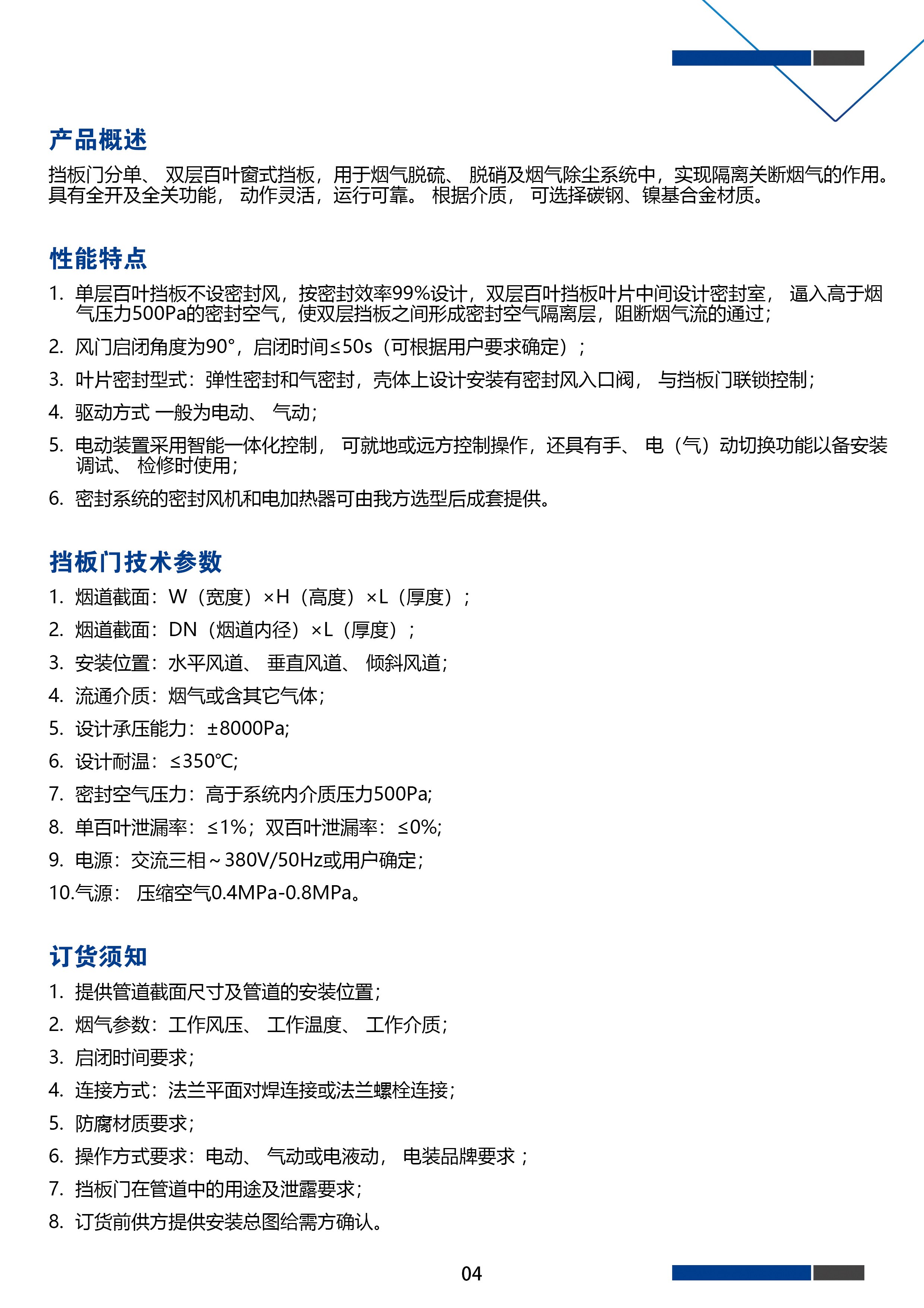
Double-louver damper specification sheet (Wincontrol 2023 brochure, p04)
| Class | Typical situations |
|---|---|
| Manufacturing | Factory quality defects such as non-flat vane surfaces degrading the mechanical seal |
| Commissioning | Site adjustment not completed: supplier reps under-skilled; short schedules with installers proceeding before vendor commissioning |
| Sealing-air system | (1) sizing errors — wrong duty data from buyer or vendor mis-sizing, insufficient pressure/flow; (2) piping design — too many bends, excessive pressure drop; (3) service wear — broken flexible connections or pipework "de-pressurising" the sealing air |
Mechanical seal adjustment (order matters): set the crank-linkage from the main vane as datum so all vane surfaces sit in one plane → adjust the seal structure until no gap remains between vanes and seal strips → put the damper to its open/closed stops and set the actuator end-position commands so actuator travel matches the damper body.
Sealing-air system: re-size and replace if mis-sized; locate and repair leaks; replace fans or parts as needed; agree sensible routing with the vendor before sizing.
After body overhaul, don’t forget to re-set the actuator end-position commands — a mismatch between mechanism travel and actuator stroke also causes "closed but leaking". Actuator pairing details in the 8 ordering parameters.
Why sealing-air systems matter · 8 ordering parameters · Damper classification · Isolation dampers
Sizing a damper? Submit an RFQ with the parameter list — same-day reply.
Source: WeChat technical article "Damper zero-leakage problems and countermeasures" (May 2018; reference: Wet FGD Handbook for Thermal Power Plants, China Electric Power Press, 2006); spec sheet from the Wincontrol 2023 brochure; compiled by actuators.cn.

An industry resource for electric & pneumatic actuators, dampers and heaters: brand manuals, sizing guides and maintenance know-how. Global brands in, China manufacturing out.