The regulating damper is the continuous flow-control device of a boiler’s air and flue-gas system — unlike an on/off isolation damper, its blades hold any position between 0° and 90° as driven by the actuator, throttling FD/ID air, secondary air, mill hot/cold air and other circuits. Structurally the multi-shaft multi-blade louver dominates rectangular ducts, with single-shaft butterfly dampers in round ducts; drives are mainly quarter-turn electric actuators. Three number groups anchor the selection: design pressure usually within ±10 kPa (a low-pressure system); ordinary carbon steel generally ≤350 °C with heat-resistant upgrades above; actuator torque = maximum differential torque × 1.25–1.5 safety factor. Product photos courtesy of Shandong Win Control Intelligent Technology (Yingkong).
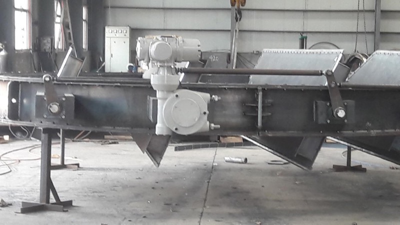
多叶片连杆联动式电动调节风门(百叶式,配角行程电动执行机构)(图源:山东盈控智能科技)
| Type | Structure | Typical size/location |
|---|---|---|
| Multi-shaft multi-blade louver (parallel/opposed) | Multiple blades in a rectangular duct linked by crank-linkage, driven from one shaft by a single actuator | Large rectangular air/flue ducts: FD/ID fans, secondary air |
| Single-shaft butterfly (round damper) | Single plate rotating 0–90° in a round duct, welded one-piece or split segments | Round hot/cold air ducts, mill inlet |
| Adjusting + isolation combination | Regulating blades in series with an isolation damper — control and shut-off separated | Ducts needing full-load SCR bypass or single-side isolation |
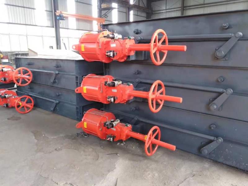
多台并列布置的电动调节挡板门(带手轮与电动执行器)(图源:山东盈控智能科技)
| Parameter | Typical range / practice (final per vendor tech agreement) |
|---|---|
| Media | Boiler combustion air, hot secondary air, primary hot/cold air, raw/clean flue gas before/after FGD, dust-removed gas (high-dust duty needs abrasion and anti-fouling blade design) |
| Design pressure | Low-pressure system — set by fan total pressure plus margin, commonly within ±10 kPa; duct design pressure and stiffening per power-plant duct design codes (e.g. DL/T 5121) |
| Working temperature (by material) | Ordinary carbon steel (Q235B etc.) generally ≤350 °C; higher gas temperatures require heat-resistant upgrades and high-temperature checks on shafts and bearings; seal strips in heat-resistant flexible materials |
| Section sizes | Rectangular ordered by internal clear size A×B (mm), from a few hundred mm to multi-metre; round by DN; all customisable to the actual duct |
| Blade count & arrangement | Set by duct section and permitted blade width; large rectangular ducts use multiple parallel shafts |
| Full-stroke time | Typically tens of seconds to one minute for 0–90°, per process requirements and actuator sizing; fast-stroke duty needs separate checks and cushions |
| Flow characteristic | Parallel blades lean toward quick-open; opposed blades approach linear — high-quality control loops prefer opposed |
| Positioning & feedback | 4–20 mA modulating with position feedback; on/off with open/close limit switches and torque protection |
| Aspect | Parallel (same-direction linkage) | Opposed (adjacent blades counter-rotating) |
|---|---|---|
| Flow characteristic | Flow rises quickly at small opening — quick-open-like curve | Staggered blades give a composite near-linear characteristic |
| Control quality | Suits on/off-dominant, lightly modulated duty | Preferred for continuous control loops (secondary air, mill inlet) — steadier at small openings |
| Structure & linkage | Same-direction linkage, simpler | Alternating-reverse linkage, slightly more complex to fabricate |
| Selection note | Choose by loop accuracy requirement — combustion auto-loops favour opposed | — |
| Drive | Matching notes |
|---|---|
| Electric actuator (mainstream) | Quarter-turn 0–90°; torque sized from maximum differential torque × safety factor (commonly 1.25–1.5); multi-shaft linkages via universal joints; modulating 4–20 mA or on/off |
| Pneumatic actuator | Cylinder or scotch-yoke quarter-turn — fast stroking and hazardous areas; positioner for 4–20 mA modulation |
| Manual (worm gear / chain) | Small sizes or maintenance isolation; worm gearbox + handwheel on large blades, electrically convertible later |
| Actuator mounting | Blade shaft end output; upright or side-mounted; linkage joints must allow thermal displacement |
Torque calculation approach: required actuator torque = maximum blade operating torque (from blade area, design differential, shaft radius and bearing friction) × safety factor (commonly 1.25–1.5). For multi-shaft linkages the linkage folds each blade-shaft torque onto the master shaft — size the actuator on the aggregated maximum. For high-differential ID-fan and secondary-air dampers take the upper bound, and specify stall protection and position feedback on the actuator.
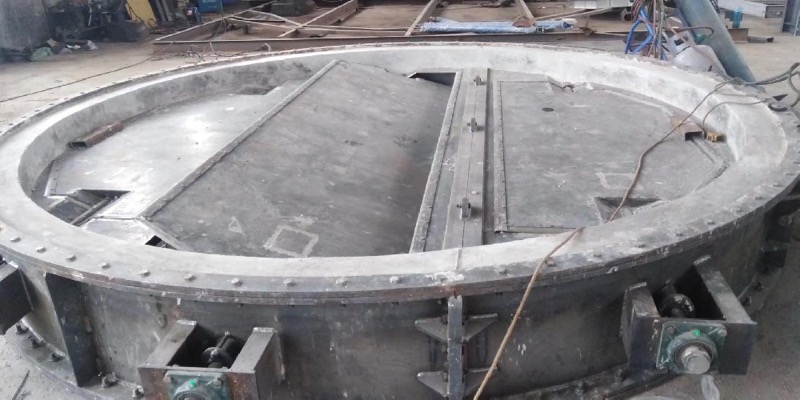
圆形风道用大直径调节风门(单轴蝶型)(图源:山东盈控智能科技)
Typical positions in a power boiler’s air/gas system: FD-fan inlet hot/cold air control, secondary-air dampers, mill hot/cold air and bypass dampers, furnace-bottom seal-air control, and bypass regulating dampers behind the ESP/ID fan. Full-load SCR retrofits also use regulating dampers on the economizer bypass for wide-load flow distribution — see our boiler air-damper tuning article in Related Reading.
| # | Please provide when ordering (sizing checklist) |
|---|---|
| 1 | Media and flow direction (cold/hot air, flue gas), dust content |
| 2 | Design pressure and operating differential range (kPa) |
| 3 | Design and operating temperature (°C) — governs materials and seal strips |
| 4 | Duct section: rectangular A×B or round DN (mm), and orientation (horizontal/vertical/inclined) |
| 5 | Regulating range and flow-characteristic requirement (0–90° continuous; parallel/opposed) |
| 6 | Full-close leakage requirement: general regulating, or isolation with seal-air system (see our seal-air article) |
| 7 | Drive (electric/pneumatic/manual), control signal (discrete/4–20 mA), full-stroke time |
| 8 | Actuator voltage/air supply and explosion-proof requirements (if any) |
| 9 | Material grades: blades / frame / shafts / bearings / seal strips |
| 10 | Connection: flanged or welded, flange standard and bolt pattern |
Note: a product-knowledge compilation; parameter ranges are common industry practice, final values per the vendor’s technical agreement. Photos from the regulating-damper page of Shandong Win Control Intelligent Technology (cgyingkong.com).
Need regulating dampers, isolation dampers and matching actuators? Submit an RFQ.






