Complete signal transmission requires resolving reference-potential differences between devices and instruments. Ideally all signals share one reference — one "earth" — indeed zero potential difference between references. In reality that is nearly impossible: beyond voltage drops along the earth interconnects, devices suffer different interference in different environments, and weathered connections degrade — so the "earths" differ. See Fig. 1.
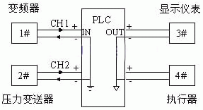
Fig. 1 PLC with external instruments
In Fig. 1 field devices 1 and 2 send signals to a PLC which signals devices 3 and 4, all 0–10 V DC. Ideally PLC and devices 1/2 share exactly the same earth potential and reception is correct. But the devices usually differ: say device 1's earth equals the PLC's while device 2's reference sits 0.1 V higher — device 1 delivers 0–10 V but device 2 delivers 0.1–10.1 V: error. Moreover the two earth leads joining at the PLC impose 0.1 V on its earth traces, potentially damaging board tracks and corrupting readings.
Earth problems recur during commissioning. One large building-materials company used a foreign PLC with a domestic manual station: each PLC acquisition board had eight channels sharing one 12-bit A/D, its digitised output isolated from the host by twelve optocouplers — but the eight inputs were not isolated from each other. Each channel alone worked; with two or more signals connected simultaneously the display jumped chaotically and the fault could not be cleared. Similarly an aerospace department measuring engine temperatures with K-type thermocouples read one point fine, but two or more points gave clearly wrong temperatures. In both cases isolators solved the problem.
Isolators work because input and output are electrically fully separated — no common "earth": an incoming 0–10 V signal, with or without common-mode interference, re-emerges as 0–10 V on a newly created "earth" unrelated to the external instruments' earths. That also isolates multiple instruments' signals from each other at the PLC — no "earth" relationship between them.
The same applies to PLC outputs driving external devices — isolators solve it too.
Another frequent case: one signal must feed both a display instrument and, say, a variable-frequency drive — the two devices may interfere with each other, so the two outputs must also be isolated. Use an isolating signal distributor: it isolates the input from external devices and the receiving devices from each other (Fig. 2).
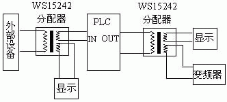
Fig. 2 Typical isolating signal distributor application
In summary, two principles solve the "earth" problem. First, electrically isolate external devices from the central processing system (PLC, DCS). Second, electrically isolate external devices from each other — both those sending to and those receiving from the central system. Follow both and interference from earth differences is fully overcome.
Most isolators need an auxiliary supply, typically 24 V DC or 220 V AC, which must be electrically isolated from both input and output. Devices isolating input/output/supply from one another are called triple-isolated or fully isolated. Theoretically one such supply can power any number of isolators without injecting interference — such products satisfy both principles.
The commonest field signals are 4–20 mA and 0–10 V; physical quantities such as pressure, temperature and flow must be converted to these for computer processing — by transmitters. Fig. 3 shows an isolated temperature transmitter with a Pt100 sensor. Since temperature is represented by resistance change, lead resistance introduces error. Transmitters like the WS9050 and WS2050 offer long-line compensation to cancel lead resistance plus linearisation for accurate conversion.
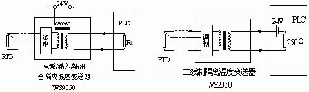
Fig. 3 Two isolated temperature transmitters
Two-wire transmitters like the WS2050 share earth between supply and output — no isolation. When several Pt100 reach a PLC through multiple WS2050s, the outputs sharing one 24 V supply are fine as long as they land on analogue inputs with a common reference — satisfying the two principles and removing earth-borne disturbance. Note: WS2050s feeding different PLCs need separate 24 V supplies.
Another isolation case: integrated sensor-transmitters that must sit at specified field locations. The isolators then sit in the central control room cabinets, powering the field transmitters. Fig. 4 shows two product wirings for different interfaces — choose per site conditions.
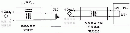
Fig. 4 Two PLC interfaces with isolating power distribution
Commissioning also meets mismatched instrument interfaces: a four-wire transmitter outputs 4–20 mA while the receiver's 4–20 mA input is two-wire loop-powered — direct connection creates a supply conflict. Fix: an isolator receives and isolates the incoming 4–20 mA, with a special output circuit matching the two-wire loop-powered input. Such isolators also handle 0–10 V, 0–5 AAC and other signals (Fig. 5).
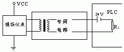
Fig. 5 WS2022 resolving supply conflicts
Ordinarily a 4–20 mA isolator needs an auxiliary supply; the WS1562 needs none (Fig. 6).
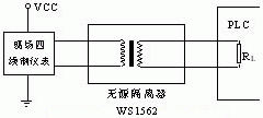
Fig. 6 Current isolator without auxiliary supply
The WS1562's chief virtues: no external supply, simple wiring, low power, high reliability — and multi-channel connections satisfying both principles.
Fig. 7 shows WS1562 output load versus input voltage at 20 mA output: VIN — input voltage; RL — load resistance; VO — voltage across RL.
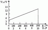
Fig. 7 Input voltage / output load curve
Fig. 8 gives linearity versus load for two passive isolators — the solid line performs better: linearity within 0.2% for RL from 0 to 500 Ω.
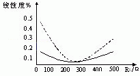
Fig. 8 Linearity / load-resistance curves
Beyond function and matching the front/end interfaces, users must weigh accuracy, power consumption, noise, insulation strength, bus communication and more.
Accuracy is vital, with many related parameters: time drift and temperature drift express accuracy stability — the smaller the better.
Noise also affects accuracy. Isolators typically use DC/DC converters for the isolated internal supply, and the input signal is modulated to pulses, crossed through the isolation barrier (optocoupler or transformer) and demodulated to the output; CPU-based isolators also carry pulses. These working pulses sit around 20–100 kHz with steep edges and rich harmonics whose pollution of signals is hard to remove. Higher noise means larger acquisition errors — so peak and energy of noise should be as small as possible.
Power consumption is the electricity used in operation, governing heat — closely tied to long-term reliability. Circuit simulation shows different consumptions heat the housing differently: working units run 10–30℃ above ambient inside the case, and over 50℃ with poor ventilation. Excessive internal temperature ages components — op-amp parameters drift, resistor values shift, capacitor leakage grows — degrading and eventually disabling the product. Mind power consumption when selecting, especially at high counts, dense installation and poor ventilation.
Isolating terminals keep shrinking to save space, allowing dense mounting — which raises the heat problem: power draw and internal temperature must come down, a precondition of reliability.
Most isolators are DIN-rail mounted with terminal wiring — "isolating terminals" — suited to cabinets, easy to rewire.






