Abstract: This paper describes the structure and working principles of the SIPOS 5 Flash PROFITRON variable-frequency intelligent actuator, including the integrated variable-frequency intelligent control unit, the signal generating device, the operating panel, terminal connection of signal and power cables, control modes, parameter setting, main-menu navigation and the initial commissioning procedure after installation.
Keywords: actuator; SIPOS 5 Flash PROFITRON; variable frequency; intelligent
SIPOS Aktorik (formerly the electric actuator division of Siemens) applies advanced and mature variable-frequency motor speed control technology to its actuators. Because a fully integrated variable-frequency intelligent control unit is built in, the complex motor-reversing control gear required by other actuators is dispensed with. The simple modular structure adapts the actuator to all control modes by adding a few necessary modules, giving reliable open/close control and variable-frequency modulating control of valves and dampers.
Besides the functions of other actuators, the SIPOS 5 Flash PROFITRON offers special features: even if the valve or damper jams, the output torque never exceeds the preset upper limit; the starting current never exceeds the rated current, so thinner cables can be used; the supply phase sequence is corrected automatically; comprehensive motor protection ensures the motor can never burn out; and the output shaft speed can be set at will. It has already been applied to control-system retrofit projects such as forced/induced draught fans, primary air pressure and feedwater-pump scoop-tube control.
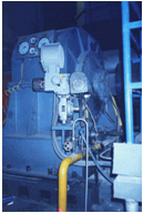
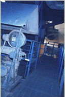
Left: scoop-tube control of a forced-draught fan coupling; right: secondary air damper control (site applications)
Very-large-scale integrated circuits replace mechanical components: no wear, maintenance-free, highly intelligent and programmable. The electronic limit protection and electronic torque protection replace mechanical limit switches and torque switches, eliminating the time-consuming switch adjustments during commissioning.
The actuator accepts four digital commands from the control system (open, close, stop and emergency) as well as a 4–20 mA DC position setpoint, and outputs one 4–20 mA DC position feedback signal and eight digital status signals. Via the LCD display, parameters are set in dialogue mode, actuator status is monitored and faults self-diagnosed.
The built-in integrated variable-frequency intelligent control unit is far superior to the motor-plus-geartrain design, simplifies the mechanical structure and meets the process requirement of running the valve at precisely controlled speed. Without any change to the internal mechanics, the output shaft speed can be set over a 1:8 range.
The rectified voltage is first smoothed by the large capacitor C on the DC link; the current-limiting resistor R in series ensures that the voltage jump at the moment of switch-on is not passed straight to the smoothing capacitor. Once the supply is connected and operating normally, a relay shorts out the resistor.

Fig. 1 Rectification, current limiting and filtering
The DC-link voltage is converted into three-phase AC of adjustable frequency and voltage to drive the three-phase motor. This is done by high-speed electronic switches at the motor terminal board — insulated-gate bipolar transistors (IGBTs).

Fig. 2 Pulse-width modulation
The high-speed switches connect each motor winding alternately to the positive and negative poles of the DC link. By precisely controlling the on-time and the voltage polarity, the sine-wave voltage needed to drive the motor is produced.

Fig. 3 Sine-wave voltage
To control polarity switching and duration continuously and precisely, each of the six IGBTs switches up to 16,000 times per second, so high-speed microprocessors and application-specific ICs are required. Motor current is measured in the conventional way, by a shunt in the negative DC link.

Fig. 4 IGBT
The microprocessor (CPU) performs all control functions: monitoring inverter and motor temperature, detecting the actuator position via the precision potentiometer, adjusting torque, receiving control signals from the control system and continuously feeding back its own status. A switch-mode power supply provides 24 V DC to the internal control unit and outputs 24 V DC externally to power the digital open/stop/close inputs. An optional externally supplied 24 V DC keeps the control unit communicating with the control system even when the single-phase or three-phase AC supply is cut off.

Fig. 5 Integrated variable-frequency intelligent control unit
Actuator data are stored in permanent EEPROM memory; a radio-interference filter provides bidirectional isolation between inverter-induced and mains-borne interference, and no backup battery is needed to keep the data.
Open, close and stop buttons operate the actuator locally; together with the LCD they give menu-driven parameter setting and commissioning. The LCD shows operating status and fault messages and performs self-diagnosis.
The actuator automatically starts and leaves or reaches the two end positions at minimum speed, so the valve is opened or seated with maximum torque while impact from inertia is avoided; the output torque never exceeds the set closing torque.

Fig. 6 Automatic output-speed adjustment
When leaving or approaching an end position, the built-in inverter automatically reduces motor frequency and voltage, hence speed, so the end position is left or reached at minimum speed (Fig. 6). The speed range is 5–40 rpm — e.g. open 14 rpm, close 28 rpm — with seven different speed steps available within the given range.
The dead band adapts itself to the quality of the control signal and the position feedback signal (Fig. 7), ensuring the highest control accuracy with the fewest starts and stops, optimising the process and reducing valve wear through fewer strokes.

Fig. 7 Adaptive dead-band adjustment
The position controller continuously compares the control signal with the position feedback signal; if the deviation exceeds the dead band, the microprocessor drives the actuator in the direction that reduces it.
The main menu comprises Language setting, the Commissioning submenu, the Observing submenu and the Diagnosis submenu. Commissioning parameters can only be changed in locPar mode after entering the 4-digit PIN code. The ↑ and ↓ keys move between menus and parameters, ENTER enters a menu, the local/remote key exits, and parameters modified with ENTER are saved. The sequence is as follows:
Press local/remote — "locPar ready" appears. Press ↓ — "Sprache/lang./idioma/lingua↑↓E"; ENTER enters language setting. Press ↓ — "commissioning↑↓E"; ENTER enters the commissioning environment. Press ↓ — "observing↑↓E"; ENTER enters observing. Press ↓ — "diagnosis↑↓E"; ENTER enters diagnosis. Press ↓ — "←return to menu↑↓E"; ENTER exits the main menu.
General settings include the display language (five languages available, normally English), the electronic anti-condensation heater-space heater (set to active), and the ID number 20 identifying the actuator (normally unused).
Valve-related parameters are listed in Table 1 and control-system parameters in Table 2.
| Table 1 Valve-related parameters | ||
|---|---|---|
| No. | Display | Meaning |
| 1 | Closing speed | Open-direction, close-direction and emergency speeds can be set separately. |
| 2 | Cut-off mode cl | Cut-off mode in each direction: torque-dependent or travel-dependent. |
| 3 | Max.cl.torque | Cut-off torque in the open and close directions. |
| 4 | Endpos.adjust | Adjustment procedure of the fully open and fully closed end positions. |
| 5 | Rec.torque graph | Recording of the valve torque curve. |
| 6 | Endpos.rang cl | Range adjustment of the two end positions. |
| 7 | Close tightly | Within the end-position range the actuator keeps moving to the very end of the end position even if the command has already terminated. |
| 8 | Maintenance per | Maintenance interval setting; not used on site. |
| Table 2 Control-system-related parameters | ||
|---|---|---|
| No. | Display | Meaning |
| 1 | Setpoint input | 4–20 mA DC signal; sets the rising or falling characteristic of the built-in controller. |
| 2 | Binary inputs | Sets the effective level of the open, close and stop commands (active low or active high). |
| 3 | Remote control | Selects the control mode in remote state. |
| 4 | Open circ.beh. | Actuator behaviour on control-signal loss: move to emergency position or hold. |
| 5 | Emergency pos. | Emergency position can be set anywhere in the stroke. |
| 6 | Travel pos.cl | Two freely programmable positions at which the actuator sends two digital feedback signals to the control system. |
| 7 | Readback output | 4–20 mA DC signal, rising or falling. |
| 8 | Binary output 1 | Eight digital outputs assignable by programming, active low or high. |
| 9 | PROFIBUS address | PROFIBUS bus address setting. |
| 10 | Enable PosCntr | 4-digit PIN code. |
| 11 | Speed local | Speed self-adaptation over the travel. |
After installation the Siemens actuator is wired as follows: 1) setpoint to X3.2 terminals 14 (+) and 15 (−), terminal 18 earth; 2) feedback to X3.1 terminals 1 (+) and 2 (−); 3) supply to X1 terminals L1, L2, L3, 380 V AC.
Switch the actuator to LOCAL. Before adjusting the travel, put the valve or damper at mid-position, remove the signal-gear-unit cover and set the centre gear by hand to a suitable position.
Determine the running direction of rotation, the rotation of the centre gear and the position of the centre gear at the end positions. Set the end positions first, then the signal gear unit ratio.
From the main menu: commissioning → PIN code → endpos.adjust → ENTER.
1) start with pos — select which end position to set first; move to op.pos with ↑/↓, press stop, and confirm the end position with ENTER.
2) adjust of poti — hold the upper part of the centre gear and rotate it slowly by hand in the direction of decreasing display value until the display reads 0; confirm with ENTER.
3) move to cl.pos — run to the other required position with ↑/↓ and confirm with ENTER.
4) sign.gear ratio & adjustment OK — ratio set, positions correct; press ENTER → "↓" → "local/remote" to exit commissioning.
The parameters that matter when installing and commissioning a Siemens actuator are: 1) CLOSE DIRECTION (rotation when closing the damper); 2) CUT-OFF MODE of the end positions; 3) the signal gear unit ratio; 4) SETPOINT INPUT type; 5) REMOTE CONTROL type; 6) OPEN CIRC BEH (open-circuit behaviour).






