Selecting an electric actuator is essentially converting valve operating parameters into actuator ratings: motion form, torque/thrust, output speed (or stroke time), power supply, protection class and control mode. This article breaks the process into nine steps with the key checkpoints for each, applicable to the routine selection of multi-turn, quarter-turn and linear electric actuators.
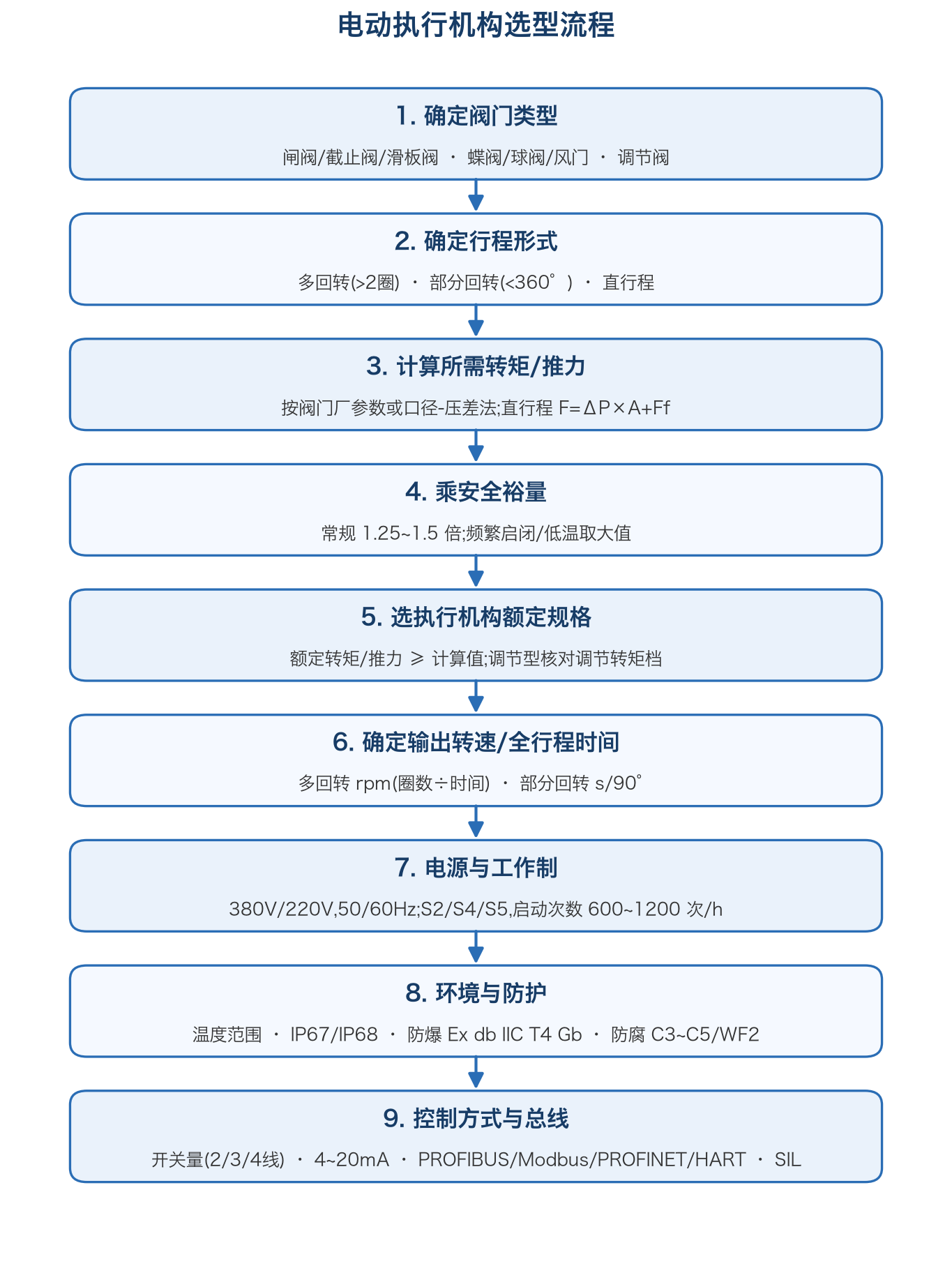
Nine-step selection flow for electric actuators
Step 1: Identify the Valve Type
The valve type determines the load characteristics: gate, globe and slide valves are multi-turn; butterfly valves, ball valves, dampers and louver valves are quarter-turn; control valves (globe, double-seat, cage, three-way) are linear. Determine the valve type first — most actuator vendors build all three motion forms on shared base units plus gearboxes.
Step 2: Determine the Motion Form
- Multi-turn: the output shaft must rotate more than 2 turns to complete the stroke — gate and globe valves
- Quarter-turn: rotation below 360° (typically 0~90°, special 120°/180° available) — butterfly valves, ball valves, dampers, louver valves
- Linear: linear output motion driving the valve stem directly or through a linear unit
Mismatch between motion form and valve is the most basic selection error — e.g. fitting a multi-turn base to a butterfly valve without a worm gearbox.
Step 3: Calculate the Required Torque/Thrust
- Prefer the maximum operating torque/thrust stated by the valve manufacturer — the most reliable source
- Without valve-maker data, estimate from valve type, bore and differential pressure, checking: the unbalanced force (torque) of differential pressure on the disc/plug, packing friction, stem-thread friction (multi-turn), and bearing/seal friction
- Linear thrust is checked as F=ΔP×A+Ff: differential pressure times effective plug area plus packing and guide friction
- For butterfly valves distinguish opening, closing and mid-stroke torque states and take the maximum; for ball valves check the "seated" torque case
Step 4: Apply the Safety Margin
Multiply the calculated value by a factor of 1.25~1.5: about 1.25 for routine duty; larger for frequent operation, low-temperature sticking, fouling media or valves that operate infrequently. Oversizing is not free — an oversized actuator imposes needless shock torque on the valve and raises purchase and power-supply costs.
Step 5: Choose the Actuator Rating
Match the step-4 result against the actuator catalogue:
- On/off duty: check the rated torque/thrust — rated ≥ calculated
- Modulating duty: also check the "modulating torque" class — many vendors rate frequent modulating below the on/off rating (e.g. rated 500Nm, modulating 400Nm); undersizing causes repeated over-torque trips
- For multi-turn check the maximum allowable axial thrust (thrust-type "A" base) when stem thrust exists
- For linear check the thrust class and stroke coverage
Step 6: Determine Output Speed / Stroke Time
- Multi-turn: speed (rpm) = valve turns ÷ required stroke time (min). Catalogues typically offer 7~56rpm sections, some models 80~160rpm; non-self-locking high-speed sections are generally not recommended for modulating duty
- Quarter-turn: expressed as stroke time (s/90°), commonly 20~60s/90°; ESD service needs models supporting high-speed settings
- Starts per hour: about 600/h for on/off and 1200/h for modulating duty covers most services; frequent modulating also requires matching duty class (S4/S5) and motor thermal capacity
Step 7: Power Supply and Duty
Common supplies are three-phase 380VAC, with 220VAC single-phase and 440/480VAC options, 50/60Hz. Motor insulation is typically class F/H; duty S2 (short-time, on/off) versus S4/S5 (repetitive, modulating) must match the starts-per-hour. For remote wells and pipelines verify the local voltage fluctuation range and phase-sequence tolerance.
Step 8: Environment and Protection
Check item by item for the installation site:
- Temperature: standard types roughly -25℃~+70℃; high-temperature up to +105℃; low-temperature -40℃; ultra-low-temperature -60℃ (with anti-low-temperature heater)
- Protection: at least IP67/IP68 outdoors; choose IP68 (20m/96h) waterproof types for submersion, with qualified sealing cable glands
- Explosion-proof: gas Ex db IIC T4 Gb, dust Ex tb IIIC T130℃ Db, matched to the hazardous-area classification
- Corrosion: C3 standard, C5/WF2 coating schemes for heavy corrosion
- Others: lightning-tested types for thunderstorm areas; EMC level for high-interference sites
Step 9: Control Mode and Fieldbus
- Digital control: 2/3/4-wire schemes for open/close; check whether the DCS output is a holding signal or a short pulse
- Analog control: 4~20mA command and position feedback for closed-loop modulating; check input impedance and load resistance
- Fieldbus: PROFIBUS-DP, Modbus RTU, PROFINET, HART, FOUNDATION Fieldbus for deep DCS integration and online diagnostics; declare redundancy requirements early
- Functional safety: SIL 2/SIL 3 certification per the safety-loop requirement
- ESD: for emergency-trip loops confirm hold-in-position/fast-open/fast-close settings
When in doubt, send the valve data sheet (type, bore, differential pressure, turns or stroke, action time, supply and environment) to the actuator vendor's technical support for review — the cheapest error correction. We hold a large library of actuator catalogues and manuals; contact us for selection documents.






