Electric actuators are widely used in flow control, changing valve opening per the controller's command. Conventional actuators — poor accuracy, large dead band, complex wiring — no longer meet modern industrial needs. With microelectronics advancing, microprocessor-based actuators emerged. This article presents a design based on the ADμC812 microconverter.
1. Basic principle
The actuator receives the control signal from the supervising system and the position feedback, computes both internally and closes the valve-position loop; it also takes motor overcurrent, internal temperature, gearbox over-torque and limit-switch signals to protect the motor (overcurrent/overheat), provide output over-torque protection and electrical end-limit.
2. Hardware design
1. MCU selection (structure in Fig. 1): with four analogue inputs, an MCU with on-chip A/D improves cost-effectiveness, plus on-chip FLASH/EEPROM for parameter setting and power-loss retention. The Analog Devices ADμC812 microconverter was chosen: an 8051/8052 core integrating a self-calibrating 8-channel 12-bit A/D, two 12-bit D/As, 8 kB FLASH, 640 B FLASH/EEPROM, 256 B RAM, watchdog, power monitor and ADC-DMA, with 32 programmable I/O lines, I2C-compatible SPI and a UART. With minimal external circuitry it forms a complete actuator controller — a very simple circuit.
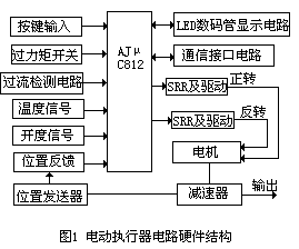
Fig.1 Actuator structure diagram
2. Analogue input (Fig. 2): the position transmitter uses a potentiometer to turn shaft angle into voltage, amplified differentially into a current signal; this and the valve-opening current from the host enter the ADμC812 A/D inputs through sampling resistors. Overcurrent is sensed without a comparator — rectified and divided directly into the A/D with software comparison; overheat uses an AD590 sensor amplified to 0.0–2.5 V, A/D-converted and compared in software for thermal protection.
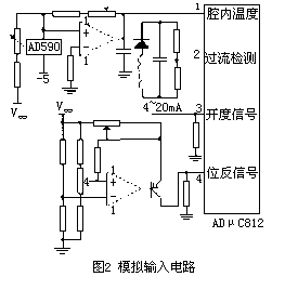
Fig.2 Analogue input circuit
3. Keypad and display: requirements — show valve opening in normal service, show probable fault causes and alarm on failure, and support parameter input. A MAX7219 serial display driver (BCD decoder, multiplex scan, segment drivers, 8×8 RAM on chip) drives a 4-digit LED display over SPI using only three I/O lines; the keypad uses ports P2.0–P2.3 directly with four keys for state changes and parameter input.
4. Output stage: control signals from port P0 are amplified by a ULN2003 and drive zero-crossing solid-state relays for forward/reverse motor control — simple, stable, grid-friendly.
5. Communication: two user-selectable interfaces — RS485 (SN75LBC185) and CAN fieldbus (SJA1000 controller + 82C250 transceiver).
3. Software
The software comprises a main program, keypad service and subroutines, written in C in modular fashion and downloaded over the serial port into on-chip FLASH. Subroutines: initialisation, data acquisition, control computation and output, status display, alarms and communication; the keypad is polled on a timer for state changes and parameter entry (program flow in Fig. 3).
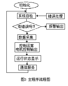
Fig.3 Program flow chart
Because of motor inertia and feedback lag, conventional control causes overshoot and frequent motor jogging. The control/output subroutine therefore uses a proportional-pulse algorithm: proportional control for large deviations between actual opening and signal, pulse control for small ones, with pulse width Tp = T×D + T0 (T: time constant; D: position-feedback deviation; T0: minimum actuator start time).
The CAN communication subroutine serves a monitoring network — one host node and several actuator nodes. The actuator transmits valve opening, parameters and alarm data: on request it packs and sends field data; on a local fault it transmits the fault data without waiting for a request. For anti-interference design, the on-chip watchdog is armed through WDTCON to monitor program execution.
4. Conclusion
Compared with conventional actuators, the ADμC812-based design offers: ① control accuracy of 1.5% — 2–4% better than traditional units — with markedly improved dynamics; ② a simple circuit with few components, mechatronic structure, high reliability and easy wiring; ③ advanced communication for easy host integration; ④ strong self-diagnostics — broken input/feedback lines, motor abnormalities, overheat and overcurrent — with cause-specific protective actions.
We supply intelligent actuators of all major brands with RS485/CAN/Profibus options and spare parts — contact us.
Source: compiled from public technical literature by this site.






