Multi-turn electric actuators were traditionally used for local and remote on-off (two-position) control. With growing automation, centralized control and programmed start-stop have become widespread, and the automatic control of high-pressure control valves in particular demands higher performance and quality from multi-turn actuators.
The SKD multi-turn electric actuator is the actuating unit of the DDZ-S instrument series. Powered from an AC supply and accepting the unified 4–20 mA DC signal, it converts the signal into corresponding multi-turn displacement of the output shaft, automatically operating gate valves, globe valves, high-pressure control valves and similar final elements.
On-off multi-turn actuators only switch the fluid flow (two-position duty) — commonly called "electric actuators" or "electric heads" — whereas modulating multi-turn actuators can also control flow continuously according to the signal. Modulating duty is frequent, typically 10–20 operations per minute, demanding more from the motor; the position transmitter output must vary linearly with valve position with defined accuracy. The SKD is a modulating multi-turn actuator with these main features:
① Servo drive motors (up to 100 N·m output torque): small-power versions use single-phase motors, high-power versions three-phase motors with brakes — good starting and braking performance;
② Suited to frequent starting (up to 10–20 operations/min) for all automatic or remote applications;
③ Torque protection and limit switches ensure reliable valve closing/opening and protect the valve and motor against overload; contact outputs are available for interlocks or alarms in the control loop;
④ Manual/auto changeover clutch with a handwheel for local operation;
⑤ Position transmitter provides a 4–20 mA constant-current DC signal;
⑥ The three-phase amplifier uses solid-state relays as its main switching elements, with signal-loss, phase-loss and overcurrent protection — reliable and interference-resistant.
Main Technical Data
Input 4–20 mA DC (2 inputs, galvanically isolated); input resistance 250 Ω; basic error ±2.5%; hysteresis 1.5%; dead band adjustable 0.5%–5%; output torque 16–600 N·m; output speed 5–20 rev/min; output travel 5–20 turns; supply 220 V AC or 380 V AC ±10%, 50 Hz; ambient temperature: actuator −25 to +70 °C, amplifier 0–50 °C; relative humidity: actuator 5%–95%, amplifier 10%–85%; atmospheric pressure 86–106 kPa; non-corrosive ambient air; enclosure protection IP65.
Working Principle and Construction
The SKD proportional multi-turn actuator consists of two structurally independent parts: the servo amplifier and the actuator. With a three-phase servo motor, a three-phase amplifier is used. The SKD electric operator is an auxiliary unit providing auto/manual changeover, manual positioning, position indication and event handling.
In automatic mode, the input current from the controller is compared in the servo amplifier with the position feedback current; the amplified error drives the three-phase motor through the three-phase power controller, and after reduction the output shaft rotates. The direction of rotation follows the polarity of the error — always towards reducing it — until the error falls below the amplifier dead band; the number of output shaft turns is linear with the input signal. In manual mode, the operator's buttons drive the three-phase motor directly through the power controller.
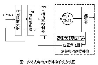
Fig.1 SKD multi-turn actuator working principle block diagram
The actuator carries travel limit switches: when the valve reaches an end position, the normally closed contact opens the contactor circuit in the three-phase power controller, disconnecting the main circuit and stopping the motor. The power controller also includes phase-loss and overload protection circuits for safe motor operation. The main components are outlined below.
1. Three-phase amplifier
The three-phase amplifier consists of a ZPE servo amplifier and a ZPK three-phase power controller. It compares the input signal with the position feedback, amplifies the error and delivers sufficient power to drive the three-phase motor.
A. ZPE servo amplifier: typically comprises a preamplifier stage, trigger circuit, signal-loss protection circuit and solid-state relays.
B. ZPK three-phase power controller: the power amplification unit, mainly composed of an LM301 logic control module, the main circuit and a phase-loss protection circuit; its schematic is shown in Fig. 2.
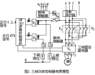
Fig.2 ZPK three-phase power controller schematic
a. Logic control module: receives the servo amplifier output and produces forward/reverse trigger signals — switching the forward/reverse contactors to reverse the motor, and gating the three-phase solid-state relays to connect/disconnect the motor main circuit.
b. Main circuit: consists of an overload protector, changeover contactors and three-phase solid-state relays. On a forward command, the LM301 first turns on SSR Q1 and energizes contactor Z1 (contacts K1 close), then gates SSR Q3 — the motor runs forward. When the command disappears, Q3 turns off first, then Q1 and Z1 de-energize and the motor stops; reverse duty works the same way via Q2, Z2 and K2. With this hybrid SSR + changeover-contactor scheme, motor connection/disconnection is handled by the contactless SSRs while the two changeover contactors only reverse phases — and they switch with the load disconnected, so no sparking or arcing occurs, improving reliability.
c. Phase-loss protection: on phase loss, the detection circuit energizes contactor Z3 — one contact gives an external alarm (or event signal), the other (K3) cuts power to Z1 and Z2, disconnecting the motor. On stall or overload, the overload protector trips and disconnects the power controller supply.
Two advantages of the single-phase-servo + three-phase-power-controller scheme: ① three-phase and single-phase supplies are separated — the servo amplifier and operator (single-phase) sit in the control room while the power controller (three-phase) sits in the field, keeping three-phase power out of the control room; ② the modular design is highly generic — three-phase duty only requires adding the power controller.
2. The multi-turn actuator
Comprises a three-phase braked motor, a gear reducer, a switch box (torque protection mechanism, travel limit mechanism and position transmitter, plus terminals) and a handwheel mechanism.
A. Three-phase braked motor: requires a soft mechanical characteristic — typically a 4-pole motor, class F insulation, rated for 10–20 operations/min (25% duty). Calculated motor power P1 = 1.02·MH·nH/(10η), where MH is rated output torque (N·m), nH rated output speed (rev/min), η total reducer efficiency; multiply by utilization factor KP (typically 1.2–1.5): P = KP·P1. The brake is usually an electromagnetic friction-disc type that engages on power loss to reduce coasting.
B. Gear reducer: typically one stage of spur gearing plus one stage of worm gearing; the drive arrangement is shown in Fig. 3.
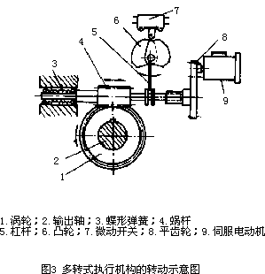
Fig.3 Reducer drive schematic
C. Switch box: torque protection mechanism, travel limit mechanism, position transmitter and terminals — common across the multi-turn series. The torque protection consists of two cam sets and two microswitches: the worm's axial creep is converted by a lever into rotary motion of a cam, which trips the microswitch and cuts the main circuit. Travel limit switches also use cam mechanisms — usually two sets, extendable to four; the adjustable cam has three layered discs, and by repositioning them any intermediate limit can be obtained. The position transmitter commonly uses a conductive-plastic potentiometer as the sensing element — reliable, stable, wide adjustment range, simple constant-current circuit and good constant-current performance — the current component of choice.
D. Handwheel mechanism: manual/auto changeover must be simple and safe. A special clutch arrangement is used, shown in Fig. 4.
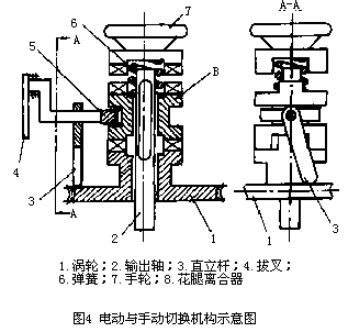
Fig.4 Manual/auto changeover clutch
In Fig. 4 the clutch is in the motor position. With the motor energized, the worm drives the wormwheel, which turns the output shaft through the spline clutch. For manual operation (motor de-energized), turn the handle to "manual" — a fork lifts the spline clutch into engagement with the handwheel — and the handwheel then drives the output shaft; the spring compresses, and an upright lever resting against the wormwheel face holds the clutch in place. To return to motor duty, simply energize the motor: as the worm turns, the upright lever tips over and the spring pushes the clutch back down into the motor position. This one-way manual→motor changeover is simple and widely used in multi-turn actuators.
Calibration and Adjustment
1. Wiring: wire the motor, switch box and three-phase amplifier per the manual or nameplate instructions.
2. Calibration and adjustment
A. Manual and automatic operation: a. Press the changeover handle in the arrow direction and confirm the clutch engages and the handwheel can operate the actuator — if not, turn the handwheel slightly left or right while pressing the handle; b. For manual→automatic changeover simply energize the motor — the handle is only for manual operation.
B. Handwheel nameplate check: confirm the open/close symbols on the nameplate match the valve's open/close directions.
C. Limit switch adjustment: the torque switches are factory-set to the ordered values and need no further adjustment (setting data per step is available from the manufacturer). Travel limit switches (full open, full close, and intermediate positions such as 50% or 75%) are adjusted the same way; the full-open example follows (see Fig. 5, two intermediate positions): ① Run the actuator towards open by hand and note the cam's direction of rotation; ② Loosen the hex nut and knurled nut; ③ At the full-open position, trip the full-open limit switch — rotate the cam in the observed opening direction until the switch trips at full open; ④ The adjustable cam has three layered discs — for full-open and full-close limits rotate the three discs together; for an intermediate limit (mid-travel or alarm), turn the discs relative to each other; ⑤ Re-tighten the knurled and hex nuts.
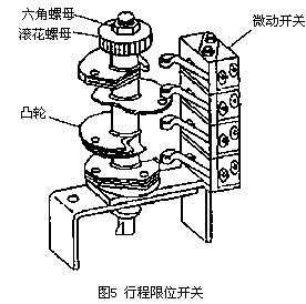
Fig.5 Travel limit switch adjustment (three-layer cam, two intermediate positions)
D. Position transmitter adjustment: a. Select the initial zero of the output shaft per the control system's requirement; b. As shown in Fig. 6, turn spur gear A meshed with the position transmitter by hand to bring the transmitter's stop to the mechanical zero, then measure the output — if not 4 mA, adjust the "zero" potentiometer to obtain 4 mA; c. Run the actuator to full open and measure — if not 20 mA, adjust the "span" potentiometer to obtain 20 mA; d. Repeat until zero and span both meet specification.
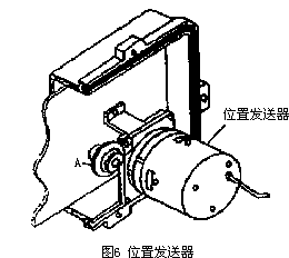
Fig.6 Position transmitter adjustment (zero and span)
3. Initial checks and first run: a. Check all wiring in order (see wiring diagrams); b. Run the actuator to mid-travel (~50%) by handwheel, then energize the motor and verify the direction — if reversed, swap two of the three motor phase wires; c. Trip the corresponding limit switch by hand and confirm the motor stops; d. Run to full close and full open and check the travel and torque limit switches are in their defined states; e. Only after these checks switch to automatic. Note: checks b and c must be done at mid-travel. For the three-phase servo amplifier, the main adjustment is the dead band per system requirements — not elaborated here.
We supply multi-turn electric actuators of all major brands together with spare parts, plus selection, calibration and after-sales support — contact us.





