Actuators are mechatronic devices common in automatic control — the "actuating" element among the three major parts of instrumentation (detection, control, actuation). Since electric actuator performance directly affects the whole control loop, mastering rapid fault diagnosis is a basic skill for instrument maintenance personnel.
1. Working Principle of the Electric Actuator
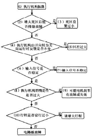
Fig.1 Electric actuator block diagram
An electric actuator mainly consists of a motor, a gear reducer, a position transmitter and a servo controller. When an input signal arrives at the servo amplifier, it is compared with the position feedback signal; if the difference exceeds the dead band (sensitivity) setting, the output shaft moves to reduce the difference until it falls below the dead band — the actuator then holds the position dictated by the input signal, automatically regulating the opening of the control valve (or damper and similar final elements).
Before the 1990s, the servo amplifier and position transmitter were separate units; from the 1990s onward, driven by advances in electronics, domestic actuators merged them into one — the now-widespread integrated servo design with much lower volume and weight.
2. Common Faults and Rapid Troubleshooting
An electric actuator involves the motor, the reducer and the electrical control section — the latter being the most likely source of faults. Diagnostic flows for the four major fault categories follow.
2.1 Actuator does not respond (no reaction to a changed command signal)
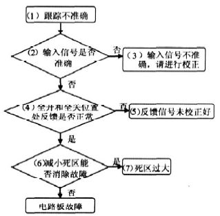
Fig.2 Troubleshooting flow for "actuator does not respond"
① Determine whether the valve (or damper) is jammed or the actuator itself is stuck — remove the actuator from the valve for a definitive check; ② Can the local handwheel operate it? If not, check for mechanical blockage; ③ Can local electric operation work? ④ Distinguish a drive-circuit-board fault from torque overload — check the alarm if available; if the unit has torque protection without alarm, verify the torque switch; for single-phase motors also check the phase-splitting capacitor; ⑤ Verify the input signal — for on-off types measure it directly with a voltmeter; for modulating types insert an ammeter in the analog input loop and compare with the demanded value; ⑥ A faulty input signal means the problem is in the control system, not the actuator; ⑦ Measure the control-board input impedance (power off, signal disconnected): generally below 500 Ω for modulating types, above 1 kΩ for on-off types with a servo board (per the manual); ⑧ Check feedback — at fully closed, fully open and mid-travel the feedback should read 0%, 100% and a value in between; ⑨ Confirm the travel has been set — if in doubt, re-set it per the manual (also called zero/span setting, end-position setting, or open/closed position setting).
2.2 Excessive valve leakage (valve still leaks considerably when the actuator is fully closed)
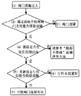
Fig.3 Troubleshooting flow for "excessive valve leakage"
① Close the valve fully with the local handwheel — before doing so, check whether the actuator has reached its mechanical zero (if so and the valve still leaks, re-adjust the relative position between valve stem and actuator output shaft); ② Then check the valve itself — damaged plug or foreign matter; ③ Check tracking error — feedback versus demand should generally be within 1.5%; ④ Re-set the travel (some actuators also have limit switches to adjust); ⑤ "Travel not set" usually means the zero (fully closed) position was set incorrectly; ⑥ If all of the above are normal, the valve may be wrongly selected — type, size, packing, etc.
2.3 Poor tracking (excessive error)
Fig.4 Troubleshooting flow for "poor tracking"
① Measure the input signal directly with an ammeter; ② If inaccurate, correct it — if correction is impossible, try replacing the corresponding I/O module; ③ Check that feedback reads 100% and 0% at full open and full close; ④ If feedback is uncalibrated, follow the manual (some actuators offer zero and span adjustment — i.e., output calibration); if this fails, re-set the travel; ⑤ Try reducing the dead band — the fault may be an oversized dead band, which is closely related to accuracy; ⑥ If the dead band is too large, reduce it per the manual; if the actuator offers no such interface, the board must be replaced.
2.4 Actuator oscillation (in automatic mode the actuator hunts around a position with an unchanged signal, or keeps cycling before settling)
Fig.5 Troubleshooting flow for "actuator oscillation"
Oscillation severely shortens actuator life. ① Try increasing the dead band — if oscillation stops, it was set too small; but a larger dead band reduces accuracy, so this is unacceptable if accuracy falls outside limits; ② Reference values: 0.75%–1.5% is common; up to 2.5% where accuracy demands are low; a 0.5% setting will inevitably oscillate owing to actuator overshoot (coasting) and signal instability; ③ Check hysteresis — in local mode run the actuator one way then the other; if the feedback changes only after a pause, hysteresis is excessive, mainly from mechanical backlash; ④ Check input signal stability — replace the I/O module if unstable; ⑤ Check coasting — after power cut the rotor's inertia lets the output shaft travel further; actuators carry brakes (contact type such as a brake disc, or non-contact electromagnetic dynamic braking); ⑥ A faulty or ineffective disc brake can usually be re-adjusted; ⑦ Check the travel setting — a travel set too small (beyond factory limits) can also cause oscillation.
We supply electric actuators of all major brands together with spare parts, plus selection, commissioning and troubleshooting support — contact us.





