Electric actuators divide into linear-stroke and quarter-turn classes. As indispensable equipment in automatic control, they convert the controller's signal proportionally into linear or angular displacement driving valves, dampers and other regulating elements — hence their wide use in power, metallurgy, petroleum and chemical automation.
Over the past decade, absorbing microcomputer control, MEMS and other new technologies, electric actuators have developed rapidly; microprocessor-based units in the "microcomputer + servo" pattern now prevail, with the microprocessor handling signal transmission, parameter switching, status indication and control output — improving flexibility of performance, use and maintenance.
Reliability is the ability to perform the required function under the specified conditions within the specified time.
"Specified conditions" summarise as:
"Specified conditions" is the most important yet most neglected part of the definition: reliability differs utterly between conditions — meaningless without them. "Required function" is expressed by torque, open/close and time, travel, dead time, dead band, etc.
The reliability pattern over service life underlies reliability study, depending on early, random and wear-out failures. Theoretically, reliability (R) — the probability of performing the required function under specified conditions and time — quantifies it. For simplicity the industry uses mean time between failures (MTBF) as the practical index.
Reliability is constrained by: system selection and design; component suitability; action parameters; mechanical construction; manufacturing technique; assembly precision; operator and maintainer competence; operating and maintenance procedures; correctness of operation; maintenance results; site assembly conditions; spare-part degradation; transport and use.
Rich functions and excellent performance force structural complexity, making reliability more prominent. Since actuators directly govern unit operation — affecting the safety and economy of the unit and plant — studying their reliability matters greatly.
Improving reliability means minimising faults — yet faults are various: some from a single component, some from combined component factors, some electrical, from secondary circuits or outside causes. Some yield to adjustment; some need repair or part replacement after long service; some need design changes.
These appear as sudden, occasional events with obvious regions and causes, from non-human and human factors: poor position-feedback contact, worn or seized brakes, damaged parts, burnt coils, failed seals.
Actuators comprise motor, bearings, gear train and electronics. US military standard MIL-HDBK-338 reliability data show actuator faults concentrate in the motor and bearings: of motor faults, winding failures 20%, bearing failures 45%, slip rings/brushes/commutators 5%, others 30%; of bearing faults, lubricant degradation or loss 45%, contamination 30%, spalling 5%, misadjustment 5%, corrosion 5%, others 10%. Good maintenance therefore complements inherent reliability and raises availability.
Actuators need lubricating oil whose viscosity varies with temperature: too thin — worm and gear wear grows and precision falls; too thick — sluggish. Cleanliness is harder still: wear debris, moisture ingress, coating flaking and rust all pollute the oil.
High cycling frequency and speed make shock unavoidable — a major cause of grease leakage. Fix leaks as soon as they appear.
Reliability and life relate directly to use, environment and staff knowledge; only better maintenance management of environment and conditions extends life.
Early faults form a high share of all faults, arising from initial design, manufacture and installation errors; finding them takes effort and fixing takes time — so maintain especially intensively then.
Random faults are hard to predict. Inspect and service periodically and keep maintenance records and historical archives — vital for accurate diagnosis and daily care.
Staff competence directly affects maintenance quality. Structural change has raised knowledge levels, yet many still lack the needed expertise — "half understanding" actuators — the weak link of maintenance management.
For easy field maintenance, actuator system design should look ahead: simplify systems; standardise and make interchangeable and easily repaired; integrate and modularise; ease adjustment and inspection; introduce fault diagnosis and location, fault tolerance/error correction.
Domestic actuators match foreign ones on some specifications, but reliability and stability long went unsolved — basic R&D neglected; commodity and foundation parts below par; weak quality control. Shanghai RuiKai Instruments therefore developed the new RK-Z series, addressing these defects. Its construction is in Fig. 1: fully enclosed, integrated, with a single-phase permanent-magnet synchronous motor — small, light, simple, low inertia, high torque. Travel limits and braking use successive-approximation electronics, achieving "soft full-open" and "soft full-close" and eliminating limit switches and brake shoes — solving the chronic problems of failing limit switches, seized brakes and motor-burning inrush currents. For reliability: reliability design, reliability testing, failure analysis, rigorous screening and ageing, and minimised moving parts — MTBF over 40,000 hours.
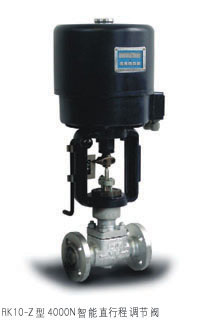
Fig. 1 RK-Z series system construction
Written in C as relatively independent subroutines for reliability and readability — easing porting and modification. Functions: receiving commands from the control centre or the local open/close keys; reading position feedback and computing control output; feeding back to the centre; displaying valve opening in real time; fault alarm and handling. See Fig. 2.
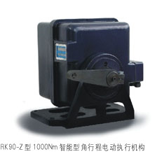
Fig. 2 Control software main flow
Actuator reliability and maintenance are vital to long-term stable control-system operation. May this article spark discussion among peers and raise actuator maintenance another step. (The author, Gao Tianyun, is a senior engineer at the East China Electric Power Test & Research Institute — byline omitted per our editorial policy.)






