Keywords: water-treatment systems; detection instruments; monitoring systems
As reform deepens and foreign-funded projects multiply, computer monitoring and control systems have entered waterworks automation. The commonest domestic architecture is a multi-level distributed system of industrial PC (IPC) + PLC + automation instruments.
In a modern waterworks every process relates to instruments and control. Instruments continuously measure process parameters, enabling manual or automatic control that coordinates supply and demand, system parts and treatment processes, so plant is used fully and rationally. Continuous comparison of measured against set values corrects deviations immediately, safeguarding water quality; dosing is further auto-controlled, pump sets run sensibly, management turns scientific and operation economical. Continuous detection with limit alarms speeds emergency handling — and instruments are the precondition of computer control. In advanced water treatment they matter immensely.
Water-supply instruments fall into two classes: process physical-parameter instruments — temperature, pressure, level, flow — where domestic products largely suffice; and water-quality analysers — turbidity, pH, dissolved oxygen, residual chlorine, SCD — a late-developing field domestically, so advanced imported products are usual, economic and reliable in the long run.
Instrument quality decides automation results. In engineering we compare performance, quality, price, spares and service repeatedly, generally combining imported and domestic instruments.
A waterworks monitoring system has two levels — plant management and field monitoring — under centralised management and distributed control. The plant computer system (master) sits in the central control room; field stations' number and location follow the process flow and structure layout. Typical surface-water stations: intake pump house; reaction/sedimentation with chlorination and dosing; filtration; treated-water pump house and substation; sludge treatment. All instrument data reach the computer system for display, control, printing, recording and alarming at the monitoring PCs.
a. Intake pump house: water quality — raw-water turbidity, pH, temperature, dissolved oxygen; operation —balancing-tank level, wet-well level, raw-water flow, per-pump and total station electricity.
b. Reaction/sedimentation, chlorination and dosing: quality — sedimentation-outlet turbidity, post-filter residual chlorine, SCD value; operation — sedimentation level, pre-settling flow, mixer-tank level, dosing-tank level, solution concentration, sludge blanket.
c. Filtration: quality — filtered-water turbidity, residual chlorine; operation — filter level, head loss, backwash flow, wash-tank level.
d. Treated-water pump house and substation: quality — output flow, residual chlorine; operation — output pressure and flow, clear-well level, wet-well level, AC voltage, AC current, electricity.
e. Sludge treatment: operation — return-tank level and flow, thickener level, return-water turbidity.
Consider: (1) the measured object — physical/chemical properties, pressure and temperature, installation, rate of level change; (2) measurement and control requirements — range, accuracy, display, local/remote indication, computer interface, safety, corrosion, constructability.
Common level meters:
a. Float type: a hollow float follows the level; its displacement is read mechanically or electrically to ±(1–2)%. Unsuitable for viscous liquids; outputs switch and continuous signals. In waterworks design, used on collecting wells to auto-start drain pumps.
b. Static-pressure (differential-pressure) type: liquid column static pressure is proportional to level — measure the pressure above a datum to obtain level. Compute the pressure range from medium density and measurement span, then choose a suitable gauge. Accuracy ±(0.5–2)%.
c. Capacitance type: an electrode in the vessel; as level changes the dielectric changes, altering the capacitance, converted to a standard DC signal — accuracy ±(0.5–1.5)%. Advantages: no moving parts, simple and reliable; high accuracy; low sensing power, fast response; easy maintenance, long life. Drawback: unstable dielectric constant causes error. Used forbalancing tank and clear-well levels. Rod, plate or coaxial electrodes to 2 m; cable electrodes beyond; insulated (polyethylene) electrodes for water.
d. Ultrasonic type: a transmitter/receiver pair — the transmitter fires ultrasonic pulses at the surface, reflections return, and time-of-flight gives distance hence level — ±0.5%. No moving parts, reliable, simple to install, non-contact, unaffected by viscosity or density — favoured for dosing tanks and sludge pools. Blind zones exist and prices are higher.
Two kinds: flow detection for process control — raising automation, improving conditions, quality and output; and flow metering for output accounting — 3 of the water industry's 8 key economic indicators rest on flowmeter data.
Selection factors: (1) national metrology certification mandatory; (2) low pressure loss; (3) accuracy not below class 2.5 per industry requirements; (4) straight-run conditions met; (5) tolerance of site temperature, humidity, electromagnetic interference; (6) suitability for the liquid.
In water-supply design electromagnetic and ultrasonic flowmeters dominate.
a. Electromagnetic flowmeters apply Faraday's law, comprising sensor and converter. The liquid itself conducts; a magnetic field is generated by two coil sets excited from AC or DC, inducing in the flowing liquid a voltage corresponding to mean velocity V, independent of flow profile. Two insulated electrodes sense the induced voltage; field, flow and electrode axes are mutually perpendicular.
Advantages: (1) unaffected by temperature, pressure or viscosity; (2) no pressure loss; (3) continuous, accurate measurement; (4) wide bore and range, continuously adjustable; (5) independent of velocity profile; (6) short straight runs — 5D upstream, 3D downstream (D = meter bore); (7) stable, standardised output, easy into DCS; (8) lined tube for corrosion and wear resistance; (9) compact, low-power converter with strong interference immunity and easy local viewing.
Linings in water treatment are usually chloroprene for wear resistance. Install away from electromagnetic field sources; in horizontal mounting keep both electrode axes level to avoid particle deposition; full pipe required — no large bubbles, or take measures.
For reliable, accurate measurement free of stray EMF, the sensor needs its own earth with resistance below 10 Ω — especially on cathodically protected pipes. On the outlet main of Tianjin's source-water plant, cathodic protection insulates inner and outer pipe walls, leaving the medium without earth reference: ground rings were fitted on the sensor end faces, insulated from the flanges; sensor and rings bonded by an earth line to an electrode; pipe flanges bonded by cable but not to the sensor; flange bolts isolated by insulated sleeves and washers. It has performed well since commissioning.
Mount converters where their protection class holds; minimise converter-sensor distance and cable length to save cost and reduce strong-signal interference.
b. Ultrasonic flowmeters entered flow measurement with recent electronics. Methods are many; the typical ones are time-of-flight and Doppler. Waterworks mostly choose time-of-flight: two transducers on the pipe; the upstream-downstream velocity difference creates a transmit-receive time difference from which velocity follows.
Advantages: (1) easy installation and maintenance — clamp-on sensors need no pipe cutting or flow interruption, ideal for large-bore lines; (2) wide bore range, price independent of diameter; (3) highly reliable; (4) no pressure loss; (5) unaffected by fluid parameters; (6) standardised DC output, easy into control systems.
Mind sensor installation error, pipe-wall scaling and lining uniformity — all strongly affect results. Per the principle, accuracy requires uniform velocity, so adequate straight runs are essential: at least 10D upstream and over 5D downstream per references and manuals.
Continuous supply makes uninterrupted metering vital, so in-line meters cannot be frequently removed for certification: a high-accuracy portable ultrasonic meter is certified periodically at a national accredited body as the enterprise standard, and in-line meters are checked against it periodically. Designers should therefore reserve comparison-measurement space per the user's future needs — making flowmeter chambers slightly larger, leaving room beside the fixed meter for the portable one, as in Fig. 1.
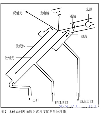
Fig. 1 Meter chamber reserving space for portable comparison metering
Turbidity quantifies water cloudiness — suspended fine particles lowering transparency. Turbidimeters measure it for water-quality monitoring and management.
Waterworks supply households and industry; quality touches public health and safety and the production of food, brewing, pharmaceuticals, textiles, printing-dyeing, power and more. Turbidity is a key index, so meter choice matters greatly. Meters divide into visual and photoelectric; photoelectric ones by use into process-monitoring (continuous) and laboratory (incl. portable), by principle into transmission and scattering (nephelometric) types.
Scattering meters sense low turbidity with high sensitivity, accuracy, low relative error, good repeatability; colour does not read as turbidity; scattered-to-incident intensity is linear — hence the WHO Drinking Water Quality Guidelines (Sept 1992) specify scattered-light meters. The "Water Supply Industry 2000 Technology Progress Plan" sets 1 NTU for class-one utilities' network water.
Common in waterworks design: HACH 1720D and SS6 series (scattered-light types).
For filtered and treated water the 1720D (formerly 1720C) prevails. Sample flows continuously through a debubbler, into the central column, rising to the measuring chamber and over its edge to drain. A focused beam projects downward into the sample; a photocell immersed in the sample measures 90° scattered light from suspended solids — proportional to turbidity. The 1720D needs no sample cell, reducing stray light and improving accuracy: ±2% over 0–40 NTU, ±5% over 40–100 NTU; resolution 0.001 NTU; response 75 s.
Filtered-water meters sit in the filter galleries, wall- or cabinet-mounted; treated-water meters in an instrument room at the treated-water pump house, signals running to the monitoring station.
Though the 1720D reads to 100 NTU, avoid pre-filter water — optically possible but impractical in service. For raw and pre-filter water use the SS6 surface-scatter series: the beam strikes the liquid surface and the scattered light from the surface is measured — no optics in the water, no signal loss from cleaning flow cells (Fig. 2). SS6 range 0–9,999 NTU, covering typical surface-water raw water; accuracy ±5% over 0–2,000 NTU and ±10% over 2,000–9,999 NTU.
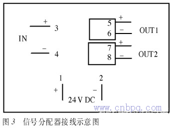
Fig. 2 SS6 surface-scatter turbidity measurement principle
Turbidity sampling points should be chosen with the process discipline — the most representative spots; sampling holes best not on the pipe crown, avoiding bubbles entering the sample line; a small sampling pump keeps flow in the line, reducing wall scaling; line diameter follows the total instrument demand.
Waterworks commonly choose intelligent display instruments: full-featured, digital signal processing, control functions, LCD readings, easy operation, data storage, self-diagnostics. Though networked computer systems eventually supersede them, intelligent displays serve as auxiliaries during commissioning or computer failure, meeting local control and display needs.
Where local display and remote transmission are both needed, avoid series connection: use a signal distributor — one input, two outputs, one to the display, one to the PLC — e.g. the common WS15242 (Fig. 3).
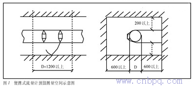
Fig. 3 Signal distributor providing local display and remote transmission
Earthing divides into protective (against electric shock from insulation failure, and equipment safety) and working (for stable, reliable instrument operation). Waterworks instrument systems usually use TN-S: phases A/B/C, neutral N and protective earth PE. Exposed conductive parts connect to PE — carrying no current normally, hence no touch voltage, easy fault clearing, strong EMC behaviour, free of harmonic interference.
Working earthing follows single-point earthing: earth-potential differences make multiple points form loops importing interference — one earth point per signal loop and per screen.
Working earth may be separate or share the protective electrode. Engineering experience: earth resistance generally ≤1 Ω.
Waterworks are dispersed, structures low, terrain flat and open — some flowmeter chambers lie outside the plant, raising lightning-strike rates. The author has repeatedly met instruments damaged by lightning or unexplained failure. Quality, reliable arresters are essential — e.g. Pepperl+Fuchs ESP series surge barriers protecting flowmeter signals and power, with good results.
(1) Modern waterworks management requires automation instruments. (2) Designers should stand in the user's shoes, selecting instruments that are stable and reliable, simple to operate, easy to install, good value, continuously measuring, responsive, interchangeable, maintainable. (3) Collect and organise technical material for digestion. (4) After commissioning, follow instruments into the field, track their use, and feed experience back into ever-better design.






