Human-machine interaction is indispensable in modern digital intelligent instruments: keyboards for operator input, LED/LCD displays for status and results — and, where industrial conditions demand, infrared remote control for setting. This article presents an HMI design combining an IR remote with an LCD for an intelligent electric actuator.
1. Characteristics of the intelligent actuator
The actuator receives the controller's analogue signal (typically 4–20 mA) or digital signal from the host and converts it into angular or linear displacement to drive control valves and dampers. Intelligent actuators built around microprocessors offer high reliability, easy operation, strong communication, complete diagnostics and wide adaptability. Beyond the microprocessor core, compared with the previous generation they feature:
(1) Convenient remote parameter setting — travel, torque and other parameters that traditionally required item-by-item manual setting can be set by remote;
(2) Rich online display — conventional mechanical valve indicators are inaccurate and failure-prone; the digital display shows valve status and opening precisely, and can indicate nine abnormal states with corresponding handling: over-maximum-torque alarm, overheat alarm, voltage abnormality, loss of current-sense signal, loss of voltage-sense signal, loss of position-sense signal, position over upper limit, position under lower limit, and loss of position setpoint signal.
The design uses a TI TMS320F240 DSP as control core, with IR remote for setting/control and an LCD for online display and fault diagnosis.
2. Main HMI components
1. IR remote and receiver: the transmitter consists of a function-key matrix, an encoding circuit (PT2262), an amplifier and IR emitters, generating pulse-amplitude-modulated IR signals per key; the receiver head amplifies the signal and the PT2272 decoder identifies the key and passes it to the DSP.
2. LCD: a TRULY 128×64 dot-matrix module with controller, scan circuitry and display RAM on board, LED backlight, single supply — built around the KS0107 controller and KS0108 drivers.
3. Hardware connection and software
1. IR receiver to DSP (Fig. 1): with only six function keys, three data lines suffice to identify which key is pressed.
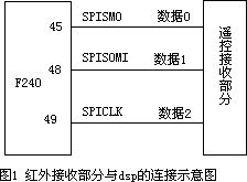
Fig.1 IR receiver to DSP connection
2. LCD to DSP (Fig. 2), direct connection: a 10 K potentiometer between pins 1 and 3 sets contrast; pin 19 through a diode to 5 V powers the backlight; pins 4 and 5 go to DSP A8/A9 to distinguish read/write and data/instruction; pin 6 (E) is the inverted AND of the read/write signals as enable; pins 15/16 select the left/right half-planes; pins 7–14 connect the data lines.
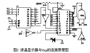
Fig.2 LCD to DSP hardware connection
3. Software: written in C, modular. The main program configures the pins and defines globals for information exchange; key codes from the IR receiver are identified and dispatched; the current opening (global Pos) is sent to the LCD — for display frequency and visual comfort the display function is called only in the real-time interrupt, refreshing the opening from the DSP every 32 ms; the same interrupt monitors operating states, prioritising faults by importance, executing protective actions or shutdown as needed and showing the fault type on screen for maintenance.
4. Conclusion
Testing showed clear advantages for parameter setting — fast, convenient, safe and reliable. With deliberately injected faults, the actuator displayed the corresponding fault states accurately and in time and handled them; after the abnormality ended, the display returned to normal and continuous operation resumed. IR setting is wireless, convenient and reliable; the LCD carries far more fault and alarm information than seven-segment displays. This HMI approach shows obvious advantages and a widening range of application.
We supply intelligent actuators with IR remote and LCD interfaces — contact us for selection advice.
Source: compiled from public technical literature by this site.






